
RS485 Fluorescence Dissolved Oxygen Sensor (Freshwater) - แท้จาก DFRobot


| รหัสสินค้า | AS00645 |
| หมวดหมู่ | วัดสภาพแวดล้อมและแก๊ส Environmental / Gas |
| ราคา | 8,950.00 บาท |
| สถานะสินค้า | พร้อมส่ง |
| จำนวน | ชิ้น |

รายละเอียดสินค้า
สินค้าใช้คู่กัน: Gravity: Active Isolated RS485 to UART Signal Adapter Module
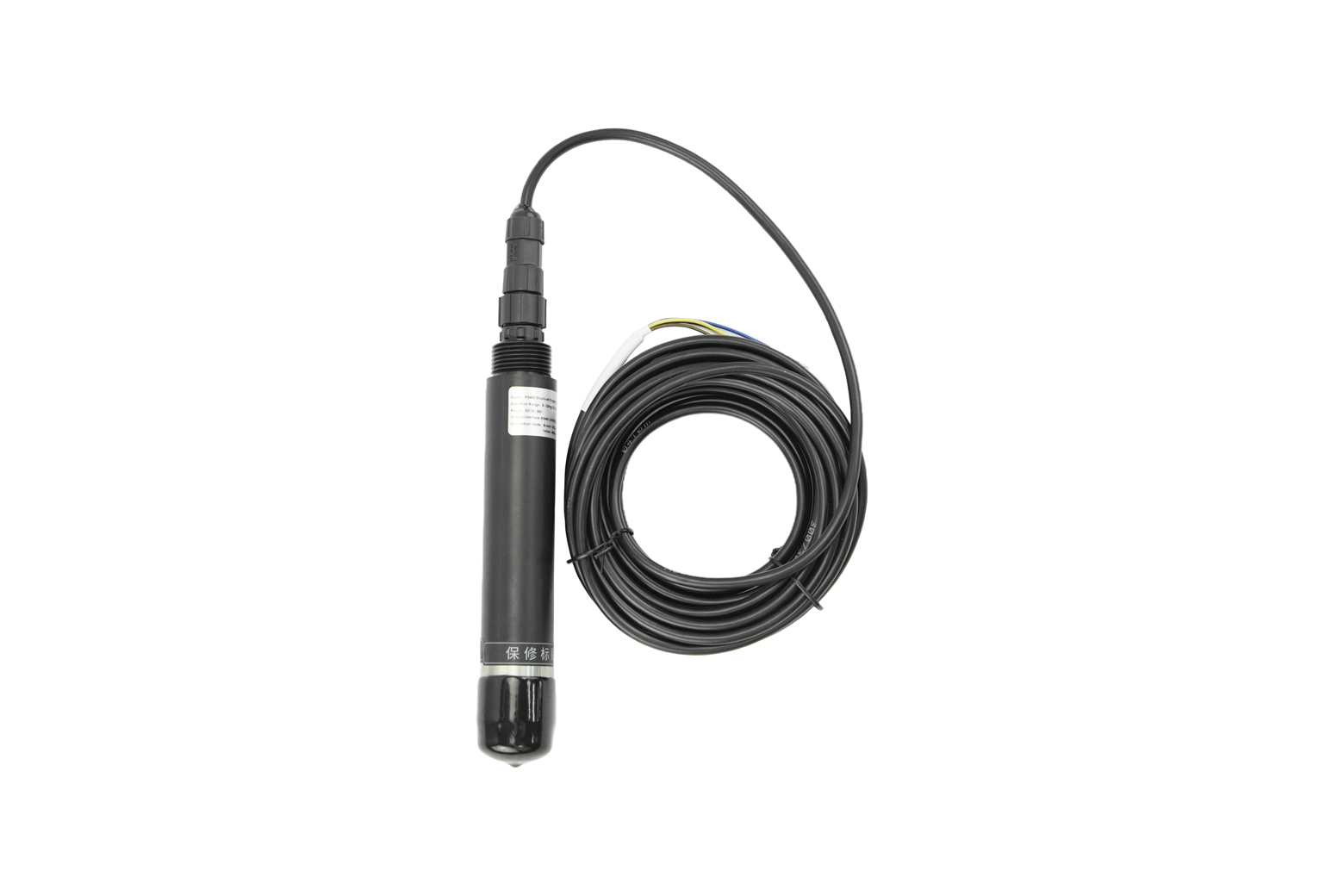
RS485 Fluorescence Dissolved Oxygen Sensor เป็นเซนเซอร์วัดออกซิเจนละลายในน้ำแบบออปติคัลที่ให้ความแม่นยำและเสถียรภาพสูง เหมาะสำหรับงานวัดในน้ำจืดที่ต้องการข้อมูลเชื่อถือได้ตลอดเวลา ใช้หลักการเรืองแสง (fluorescence quenching) ซึ่งไม่สิ้นเปลืองออกซิเจนและต้องการการบำรุงรักษาน้อยกว่าวิธีอิเล็กโทรเคมีแบบดั้งเดิม ช่วงการวัดครอบคลุม 0–20 mg/L (0–200% saturation) พร้อมระบบชดเชยอุณหภูมิอัตโนมัติในทุกการอ่านค่า ช่วยให้ค่าที่ได้มีความถูกต้องแม้สภาพแวดล้อมเปลี่ยนแปลง การสื่อสารผ่าน RS485 (ModBus-RTU) ทำให้เชื่อมต่อกับ PLC, data logger และระบบมอนิเตอร์ได้อย่างสะดวก ตัวโพรบผลิตจากสเตนเลส 316 และมีระดับป้องกันน้ำ IP68 รองรับการติดตั้งระยะยาวในฟาร์มเพาะเลี้ยงสัตว์น้ำ ระบบบำบัดน้ำเสีย แหล่งน้ำธรรมชาติ และงานวิจัยด้านสิ่งแวดล้อม
Introduction
The RS485 Fluorescence Dissolved Oxygen Sensor (Freshwater) provides a high-stability solution for measuring dissolved oxygen, designed specifically for freshwater environments. It operates on the principle of fluorescence quenching, an optical method that measures the phase shift of light caused by oxygen molecules. This optical DO probe delivers a high-accuracy measurement range of 0-20 mg/L (0-200% saturation) with an error of just ±3% FS. Key advantages include its maintenance-free optical design, built-in automatic temperature compensation, and simple system integration via the standard ModBus-RTU protocol. With a robust IP68 waterproof rating, this water quality instrument is engineered for demanding applications in freshwater aquaculture, wastewater treatment, and long-term environmental monitoring.

Maintenance-Free Fluorescence Principle
Traditional electrochemical sensors require frequent calibration and electrolyte replacement due to electrode polarization and depletion. This fluorescence dissolved oxygen sensor utilizes an advanced optical method that does not consume oxygen or rely on electrolytes. This design results in excellent long-term stability, significantly reduces maintenance frequency, and lowers the total cost of ownership.
Accurate Data with Automatic Temperature Compensation
Dissolved oxygen levels are highly dependent on water temperature. This ModBus DO sensor integrates a dedicated temperature sensor to monitor water conditions in real time. It automatically applies temperature compensation to every measurement, ensuring accurate and reliable dissolved oxygen concentration and saturation readings, even in environments with fluctuating temperatures.
Seamless System Integration via RS485
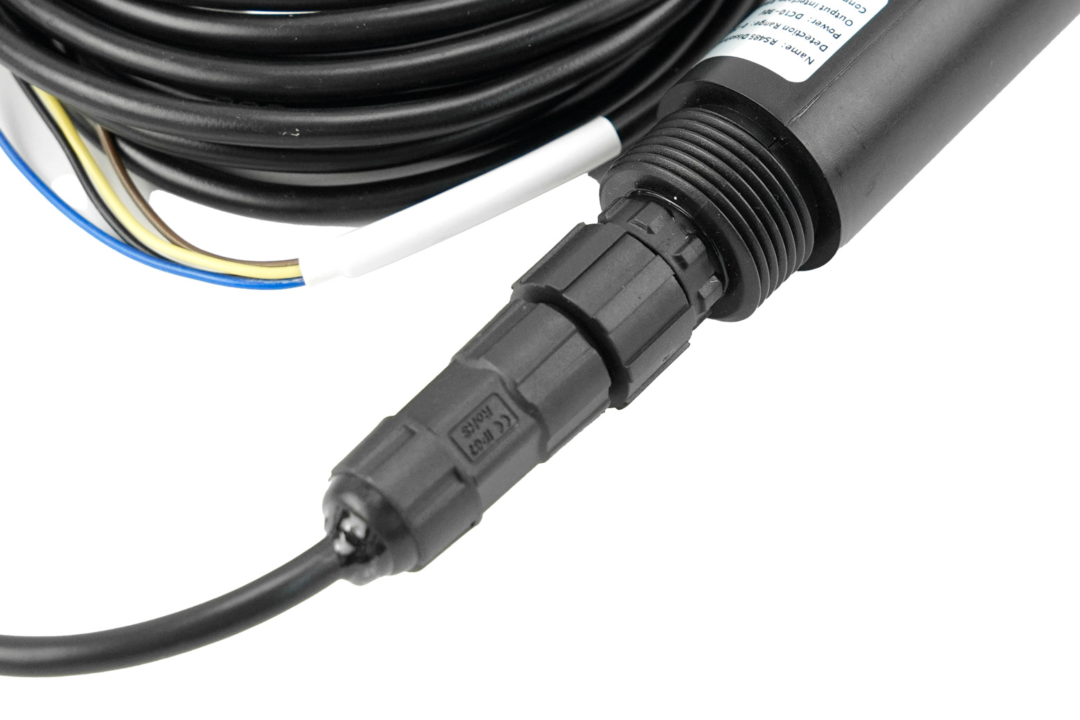
The industrial-grade sensor is equipped with an RS485 communication interface and supports the standard ModBus-RTU protocol. This feature allows for reliable, long-distance data transmission and simple integration into existing data platforms, PLCs, data loggers, or other industrial control and monitoring systems. The unit comes factory-calibrated and also supports user-defined zero-oxygen and full-scale calibration via registers for optimization.
Robust Design for Harsh Environments
Engineered for long-term field deployment, the dissolved oxygen sensor is built to last. The probe is constructed from 316 stainless steel, offering superior resistance to corrosion. The entire unit is sealed to an IP68 waterproof rating, ensuring it can be continuously submerged and operate reliably in challenging freshwater conditions, including rivers, lakes, and treatment facilities.

Applications
- Freshwater Aquaculture: Monitor DO levels in ponds and tanks.
- Wastewater Treatment: Control aeration efficiency.
- Environmental Monitoring: Long-term deployment in rivers & lakes.
- Scientific Research: Accurate DO data for field and lab work.
- Smart Agriculture & Hydroponics.

Specification
- Power Supply: DC10–30V
- Power Consumption: 0.2W
- Communication: RS485 (ModBus-RTU)
- Measurement Principle: Fluorescence
- Range: 0–20 mg/L / 0–200% saturation
- Error: ±3% FS; ±0.5°C
- Resolution: 0.01 mg/L; 0.1%; 0.1°C
- Response Time: ≤60s
- Operating Temp: 0–40°C
- Fluorescent Film Lifespan: ~1 year
- Waterproof: IP68
- Pressure Resistance: 0.6 MPa
- Cable Length: 5m
- Material: Corrosion-resistant plastic
Documents
Shipping List
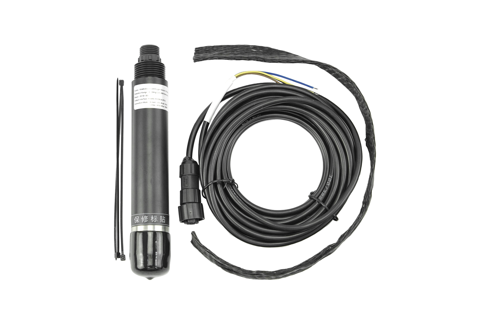
- Fluorescence DO Sensor × 1
- 5m Cable × 1
- User Manual × 1
Fluorescence measurement:
Fluorescence measurement is based on the principle of fluorescence quenching. Blue light strikes a fluorescent substance, exciting it and causing it to emit red light. Because oxygen molecules can absorb this energy (a quenching effect), the duration and intensity of the excited red light are inversely proportional to the oxygen concentration. By measuring the phase difference between the excited red light and reference light and comparing it with an internal calibration value, the oxygen concentration can be calculated.
Dissolved Oxygen Saturation Concentration Temperature Comparison Table
| Temperature (°C) | Dissolved Oxygen (mg/L) | Temperature (°C) | Dissolved Oxygen (mg/L) |
|---|---|---|---|
| 0 | 14.64 | 18 | 9.46 |
| 1 | 14.22 | 19 | 9.27 |
| 2 | 13.82 | 20 | 9.08 |
| 3 | 13.44 | 21 | 8.90 |
| 4 | 13.09 | 22 | 8.73 |
| 5 | 12.74 | 23 | 8.57 |
| 6 | 12.42 | 24 | 8.41 |
| 7 | 12.11 | 25 | 8.25 |
| 8 | 11.81 | 26 | 8.11 |
| 9 | 11.53 | 27 | 7.96 |
| 10 | 11.26 | 28 | 7.82 |
| 11 | 11.01 | 29 | 7.69 |
| 12 | 10.77 | 30 | 7.56 |
| 13 | 10.53 | 31 | 7.43 |
| 14 | 10.30 | 32 | 7.30 |
| 15 | 10.08 | 33 | 7.18 |
| 16 | 9.86 | 34 | 7.07 |
| 17 | 9.66 | 35 | 6.95 |
Tutorial
Requirements
-
Hardware
- UNO R3 (or similar) x 1
- Gravity: Active Isolated RS485 to UART Signal Adapter Module x1
- RS485 Dissolved Oxygen Sensor x1
-
Software
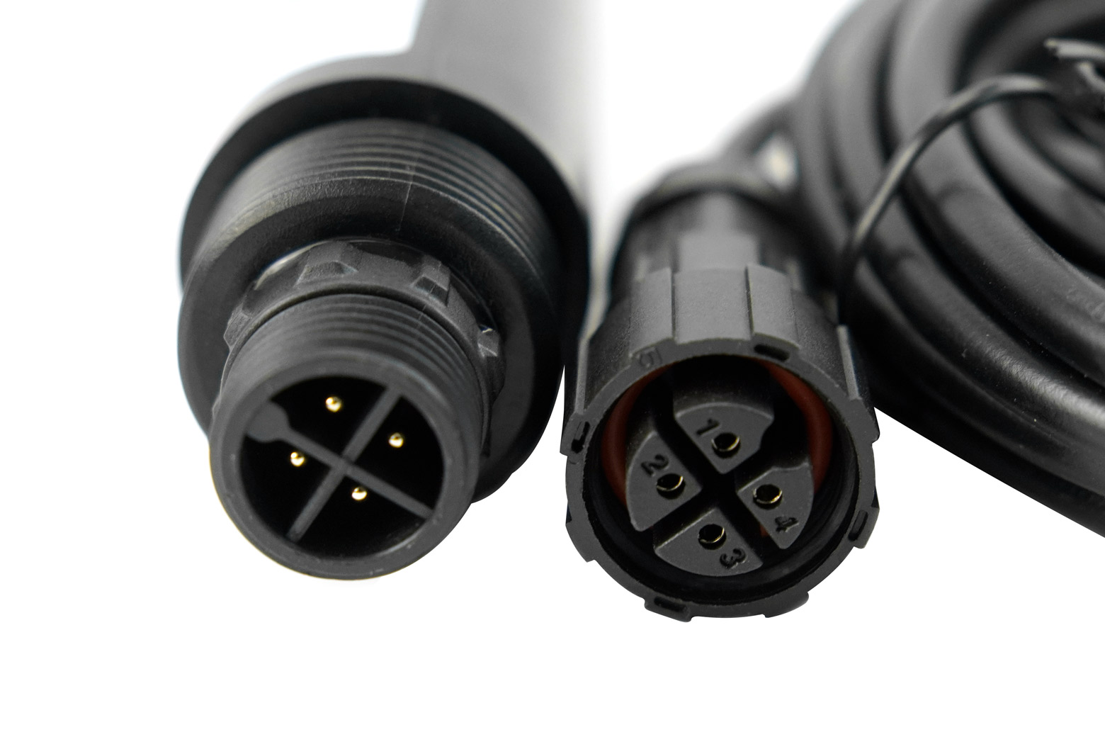
Connection Diagram
If the power of the RS485 device is small and the required current is less than 12V-160mA, the RS485 to UART signal conversion module does not require a 12V external power supply, making wiring more convenient.
Sample Code
Expected Results

Calibration Instructions
1. Calibration Preparation
Zero Oxygen Standard Solution Preparation: In a windless, sun-proof location, take enough pure water (distilled or deionized) to cover the stainless steel parts of the device. Add 5g of anhydrous sodium sulfite to every 95g of water and stir thoroughly to dissolve to create a 5% sodium sulfite solution. Let stand for 1 hour to ensure that the oxygen in the solution is completely consumed. If possible, add a trace amount of cobalt chloride as a catalyst.
100% Oxygen Environment Preparation: In a windless, sun-proof location, take enough pure water (distilled or deionized) to cover the stainless steel parts of the device. Using an air pump, continuously introduce air into the water for 1 hour. Then, let it stand for 30 minutes to create air-saturated water. Alternatively, in a windless, sun-proof location, take a small amount of water in a sealed container and shake vigorously for 30 seconds to create water-saturated air. During calibration, keep the device's fluorescent film approximately 1cm above the water surface to ensure it is moist but free of water droplets.
2. Start Calibration
Place the sensor in a 100% oxygen environment. After the dissolved oxygen value stabilizes, send the 100% saturation calibration command to complete the 100% oxygen saturation calibration.
Then place the sensor in zero oxygen standard solution, gently stir to accelerate the response, and let it sit. After the dissolved oxygen value stabilizes, send the zero oxygen calibration command to complete the zero oxygen calibration.
Note: The sensor should be allowed to sit for a sufficient period of time in each calibration environment to ensure that the sensor temperature is consistent with the ambient temperature.
Installation
The sensor should be installed below the liquid surface. Avoid bumping or scratching the fluorescent membrane during installation and use. Keep the fluorescent membrane away from sediment. Remove the rubber protective cover before use.
Precautions and Maintenance
◆ If the device exhibits obvious malfunctions, do not open it and attempt to repair it yourself. Contact us immediately!
◆ Avoid bumping or scratching the fluorescent membrane on the front of the device. Any damage will reduce measurement accuracy or even render it unusable. ◆ Avoid using organic solvents and avoid using organic solvents to clean the fluorescent cap.
◆ When installing the device, avoid excessive tension or stress on the cables.
◆ Device Cleaning:
The exterior surface of the device can be cleaned with tap water and a damp soft cloth. Stubborn dirt can be removed by adding some household detergent to the tap water.
For the exterior surface of the fluorescent cap, rinse any dirt from the sensor's optical window with clean water. If wiping is necessary, wipe gently with a soft cloth and avoid scratching vigorously to prevent damage to the fluorescent film, which can lead to inaccurate measurements or inability to measure. If dust or moisture enters the fluorescent cap, remove the cap and rinse the interior surface and the device's optical glass window with tap water. If there is grease or oil, rinse with tap water mixed with household detergent. Rinse off the detergent and wipe all cleaned surfaces dry with a lint-free soft cloth. Place in a dry place to allow the moisture to evaporate completely. Cleaning every 30 days is recommended.
◆ Before measuring, remove the black rubber protective cover.
◆ During long-term storage, add water to the sponge in the protective case and squeeze out any excess water to keep the phosphor film moist. Keep the temperature above 0°C to prevent freezing and damage. For dry storage, the lowest temperature can be -10°C. Before use, soak the device in water for 48 hours to restore the phosphor film's response.
◆ It is recommended to replace the phosphor film annually.
◆ Calibrate the device before each measurement. For long-term use, calibrate every three months. The calibration frequency should be adjusted based on application conditions (such as the degree of dirt and chemical deposits).
FAQ
- The computer has multiple COM ports, and the selected port is incorrect.
- The device address is wrong, or there are devices with duplicate addresses (all factory defaults are 1).
- Baud rate, check mode, data bit, stop bit error.
- Host polling interval and waiting response time are too short, both need to be set above 200ms.
- 485 bus is disconnected, or A and B lines are connected in reverse.
- Too many devices or too long wiring, power supply should be provided nearby, 485 enhancer should be added, and 120Ω terminal resistance should be added.
- USB to 485 driver is not installed or damaged.
- Equipment is damaged.
Note: To ensure the accuracy of the equipment, please clean the lower surface of the measuring area of the equipment regularly to keep it clean and free of dust or other foreign matter.
วิธีการชำระเงิน
ชำระเงินค่าสินค้าโดยการโอนเงินเข้าบัญชีธนาคาร KBANK, SCB, BBL,TMB
กรุณาเก็บหลักฐานการโอนเงินของท่านไว้เพื่อแจ้งการชำระเงินด้วยค่ะ
ท่านสามารถแจ้งการชำระเงินผ่านระบบอัตโนมัติได้โดย Click Link ข้างล่างค่ะ
https://www.arduitronics.com/informpayment
ชำระเงินผ่านธนาคาร


@rfm0967y
ติดต่อสอบถาม
Join เป็นสมาชิกร้านค้า
MEMBER
