
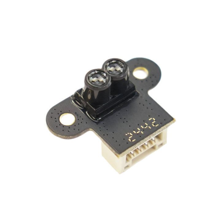
Ultra-Compact ToF Laser Ranging Sensor (7.8m, 1 gram) - DFRobot
| รหัสสินค้า | AS00636 |
| หมวดหมู่ | LIDAR / เซ็นเซอร์วัดระยะทาง / ความเร็ว Distance / Speed |
| ราคา | 985.00 บาท |
| สถานะสินค้า | พร้อมส่ง |
| จำนวน | ชิ้น |

รายละเอียดสินค้า
ตัวอย่างการประยุกต์ใช้งาน
- การนำทางโดรน: ควบคุมระดับความสูงแบบเรียลไทม์และหลีกเลี่ยงสิ่งกีดขวางในพื้นที่ในอาคารที่จำกัด
- หุ่นยนต์: วางแผนเส้นทางแบบไดนามิกสำหรับ AGV (ยานพาหนะนำทางอัตโนมัติ) หรือหุ่นยนต์บริการ
- ระบบจราจรอัจฉริยะ: ตรวจสอบการไหลของยานพาหนะและสถานะการจอดรถ
- ระบบอัตโนมัติในอุตสาหกรรม: ตรวจจับระดับวัสดุและนับจำนวนวัตถุในสายการผลิต
ดูรายละเอียดการใช้งานและตัวอย่าง code ได้ที่ Click

High-Speed Dynamic Ranging
- Drone Navigation: Real-time altitude hold and obstacle avoidance in confined indoor spaces.
- Robotics: Dynamic path planning for AGVs (Automated Guided Vehicles) or service robots.
- Smart Traffic Systems: Vehicle flow monitoring and parking status detection.
- Industrial Automation: Material level detection and production line object counting.

- Ranging Range: 0.02–7.8m
- Accuracy: ±4cm (typical)
- Refresh Rate: 50Hz
- Ambient Light Resistance: 100,000 lux
- Field of View: 2–3°
- Power Supply: 4.3–5.2V DC
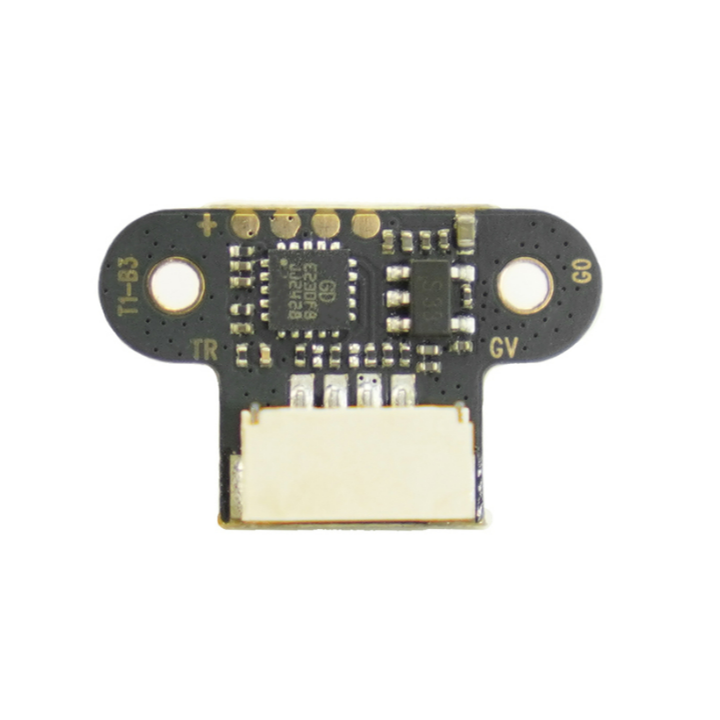
- Communication Interfaces: UART/I2C/IO
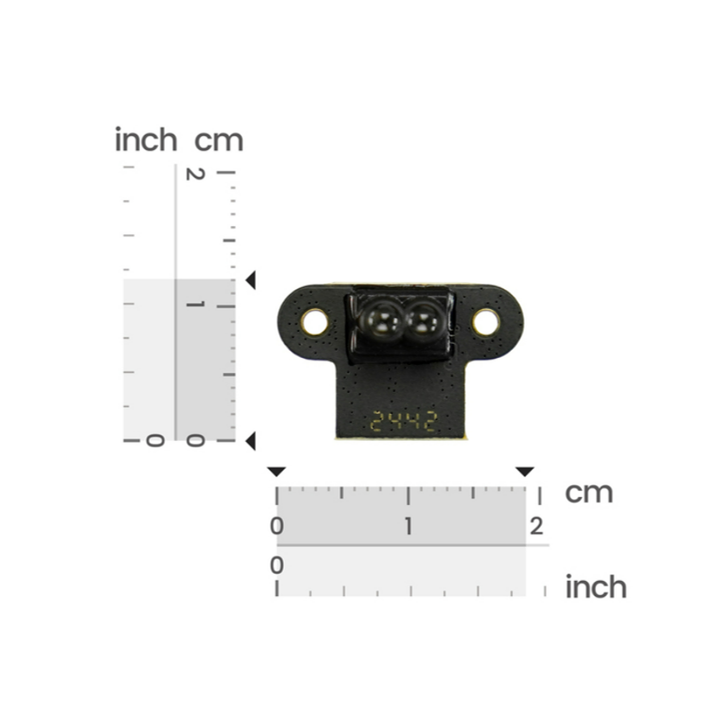
- Dimensions: 19.0×12.0×10.3mm
- Sensor Weight: 1g
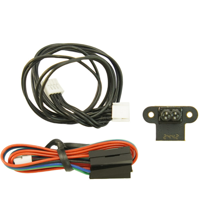
Shipping List
- ToF laser ranging sensor-7.8m x1
- Wiring x2
Usage Tutorial
Preparation
- Hardware
- TOF Laser Ranging Sensor-7.8 meters
- ESP32 Series Development Board
- Software
- Sensor Host Machine, click to download the host machine
- Arduino IDE, click to download Arduino IDE
Serial Output
UART mode has two output modes: Active Output and Query Output, which can be switched by modifying the data output mode on the host machine software. Connect the TOFSense-F/F2 series products to the host machine software through the USB to TTL module (refer to the data manual for line sequence and power supply voltage), after successful identification, click ![]() to enter the setting page, configure the parameters and click the write parameter button to save the parameters, after writing the parameters successfully, you can read the parameters once to confirm whether the parameters are written successfully.
to enter the setting page, configure the parameters and click the write parameter button to save the parameters, after writing the parameters successfully, you can read the parameters once to confirm whether the parameters are written successfully.
Active Output
UART active output mode can only be used in single module.
The interface type is set to UART, the data output mode is set to ACTIVE, and the UART active output mode is configured as shown in the figure. In this mode, the module outputs measurement information actively at a default frequency of 50Hz, and the output format follows the NLink_TOFSense_Frame0 protocol.

Wiring Diagram

Sample Code
Output Results

Query Output
UART query output mode can be used in single module.
The interface type is set to UART, the data output mode is set to INQUIRE, and the UART query output mode is configured as shown in the figure. After writing the parameters, the data will no longer be reported actively. In this mode, the controller needs to send a query command containing the module ID to the expected query module, and the module can output a frame of measurement information. The query frame format follows the NLink_TOFSense_Read_Frame0 protocol, and the output frame format follows the NLink_TOFSense_Frame0 protocol.

Wiring Diagram
Sample Code
Output Results

IIC Output
IIC mode can be used in single module and cascade. In IIC communication mode, the controller sends a read frame to the expected query module with the specified slave address according to the IIC communication timing, and can obtain the distance and other related information of the module. In addition, you can also change the module's output mode and other parameters through IIC communication. The read frame and write frame formats follow the NLink_TOFSense_IIC_Frame0 protocol.
When the module is in UART mode (note that the host machine cannot recognize the module in IIC mode), connect the TOFSense series products to the host machine software through the USB to TTL module (refer to the data manual for line sequence and power supply voltage), after successful identification, click ![]() to enter the setting page, IIC output mode configuration is as shown in the figure, you can change the IIC slave address of the module by setting the module's ID (7-bit slave address is 0x08+module ID, ID setting range is 0~111), after configuring the parameters, you need to click the write parameter button to save the parameters. Note: After switching to IIC mode, if you need to change Band_Start, Bandwidth and other parameters, you can refer to the way in the FAQ section to change back to UART mode for configuration.
to enter the setting page, IIC output mode configuration is as shown in the figure, you can change the IIC slave address of the module by setting the module's ID (7-bit slave address is 0x08+module ID, ID setting range is 0~111), after configuring the parameters, you need to click the write parameter button to save the parameters. Note: After switching to IIC mode, if you need to change Band_Start, Bandwidth and other parameters, you can refer to the way in the FAQ section to change back to UART mode for configuration.
[!WARNING]
Please remember your baud rate (Baudeate) before modifying the configuration, so that you can switch back to UART mode later.

Wiring Diagram
Arduino Sample Code
Output Results
I/O Output
In I/O output mode, it can only be used in single module, the module cannot output ranging value, TX/CAN_L and RX/CAN_H output complementary level, the level state of the two signal lines is opposite, high level is 3.3V, low level is 0V, in addition, it should be noted that the output current is small, when driving other devices, it should be noted whether it can drive, if it cannot drive directly, it can be driven by relays and other ways.
When the module is in UART mode (note that the host machine cannot recognize the module in I/O mode), connect the TOFSense series products to the host machine software through the USB to TTL module (refer to the data manual for line sequence and power supply voltage), after successful identification, click ![]() to enter the setting page, configure the parameters and click the write parameter button to save the parameters. Note: After switching to I/O mode, if you need to change Band_Start, Bandwidth and other parameters, you can refer to the way in the FAQ section to change back to UART mode for configuration.
to enter the setting page, configure the parameters and click the write parameter button to save the parameters. Note: After switching to I/O mode, if you need to change Band_Start, Bandwidth and other parameters, you can refer to the way in the FAQ section to change back to UART mode for configuration.
[!WARNING]
Please remember your baud rate (Baudeate) before modifying the configuration, so that you can switch back to UART mode later.
Single Threshold
The interface type is set to IO, Band Start is set to 1000, Band Width is set to 0, IO single threshold configuration is as shown in the figure, after writing the parameters, the module will restart and no longer output ranging value but output high and low level.
According to the above settings, the threshold=Band Start=1000(mm), in this mode, when the ranging value<1m, RX is high level, TX is low level, when the ranging value>1m, RX is low level, TX is high level.
Example: When the ranging value is 0.3 meters, RX is high level, TX is low level, when the ranging value increases to 1.2 meters, RX is high level, TX is low level.

Double Threshold
The interface type is set to IO, the hysteresis start point Band Start is set to 1000, the hysteresis width Band Width is set to 500, the IO double threshold configuration is as shown in the figure, after writing the parameters, the module will restart and no longer output ranging value but output high and low level.

According to the above settings, this mode converts the distance value into high and low level output through hysteresis comparison. When the distance changes from small to large and exceeds the high threshold, or from large to small and is lower than the low threshold, the I/O port level is reversed.
For example, based on the above settings, the low threshold is 1 meter, the high threshold is 1.5 meters. (Low threshold=hysteresis start point Band Start, high threshold=hysteresis start point Band Start+hysteresis width Band Width)
When the ranging value is 0.3 meters, RX is high level, TX is low level,
When the ranging value increases to 1.2 meters, RX is high level, TX is low level,
When the ranging value continues to increase to more than 1.5 meters, the level is reversed, RX is low level, TX is high level.
When the ranging value drops from more than 1.5 meters to 1.2 meters, RX is low level, TX is high level,
When the ranging value continues to drop to less than 1 meter, the level is reversed, RX is high level, TX is low level.
Hysteresis comparison schematic diagram is as shown in the figure

Frequently Asked Questions
Why can't the host machine software recognize the module after switching to IIC or I/O mode? How to switch between different communication modes?
Currently, the host machine software only supports the recognition of modules in UART mode. In UART mode, you can configure the module as IIC or I/O communication mode by entering the setting page after successfully recognizing the module on the host machine; in IIC communication mode, you can switch back to UART or I/O mode by sending commands to the module through IIC communication according to the IIC communication protocol; in addition, you can switch back to UART mode in the following ways without IIC test environment or after switching to I/O mode:
- Users need to prepare a USB to TTL module that supports a baud rate of 921600 (CP2102 is recommended) and install the corresponding driver program. Connect the TX, RX, and 5V three wires of the USB to TTL module to the corresponding pins of the TOF module, and do not connect the GND pin for the time being. Then plug the USB to TTL module into the computer.
- Open the host machine software, click
 icon to enter the serial port debugging assistant, change the baud rate to the baud rate you set before (if the baud rate has not been modified, it is 921600), select the COM port corresponding to the USB to TTL module and then click
  connect button to connect the COM port (in most cases, it will connect automatically), enter 54 20 00 ff 00 ff ff ff ff 00 ff ff 00 10 0e ff ff ff ff ff ff ff ff ff ff ff 00 ff ff ff ff 7c in the single send text box, change the send interval to 20ms in the timed send bar at the bottom right, and then check timed send.
- At this point, connect the GND of the USB to TTL module to the GND pin of the TOF module, the module will switch to UART mode and start outputting data, at this point uncheck the timed send button, then unplug the USB to TTL module and repower the module, then click the
 identify button on the main page to identify the module.
 - If the switch fails, unplug the USB to TTL module and repeat the whole process. Do not unplug and plug the GND pin multiple times while sending commands. If the module can be recognized normally but the serial port output data is abnormal, you can manually change to UART mode in the setting page.
วิธีการชำระเงิน
ชำระเงินค่าสินค้าโดยการโอนเงินเข้าบัญชีธนาคาร KBANK, SCB, BBL,TMB
กรุณาเก็บหลักฐานการโอนเงินของท่านไว้เพื่อแจ้งการชำระเงินด้วยค่ะ
ท่านสามารถแจ้งการชำระเงินผ่านระบบอัตโนมัติได้โดย Click Link ข้างล่างค่ะ
https://www.arduitronics.com/informpayment
ชำระเงินผ่านธนาคาร


@rfm0967y
ติดต่อสอบถาม
Join เป็นสมาชิกร้านค้า
MEMBER
