
ESP32-S3 AI Camera Module (Edge Image Recognition, Night Vision, ChatGPT Voice Interaction) - แท้ DFRobot
| รหัสสินค้า | AS20562 |
| หมวดหมู่ | โมดูลวัดสี กล้องและการมองเห็น Camera / Color / Vision |
| ราคา | 1,185.00 บาท |

รายละเอียดสินค้า
ดูตัวอย่างการใช้งานและ arduino code ได้ที่ Click
Introduction
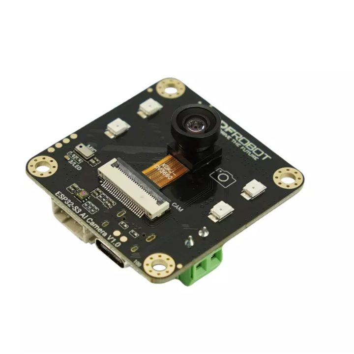
The ESP32-S3 AI Camera is a cutting-edge intelligent camera module built around the high-performance ESP32-S3 chip, designed for efficient video processing, edge AI, and voice interaction. Featuring a wide-angle infrared camera, onboard microphone, and speaker, it is ideally suited for applications such as electronic peepholes, baby monitors, and license plate recognition. With powerful AI processing capabilities, it integrates seamlessly into IoT ecosystems, supporting edge image recognition and online AI model interaction through Wi-Fi connectivity, making it an essential component for IoT applications, from security surveillance to AI assistants.
Intelligent AI Processing and Edge Computing
The ESP32-S3 AI CAM utilizes the powerful neural network capabilities of the ESP32-S3 chip for edge-based image recognition with platforms like Edge Impulse, YOLOv5, and OpenCV. It supports efficient on-device processing for tasks such as object detection and image classification, while integration with ChatGPT enables voice-controlled command execution. This combination of local AI processing and cloud-based model access makes the module ideal for a wide range of IoT applications.
To ensure easy integration, the ESP32-S3 AI CAM comes with extensive tutorials, documentation, and sample code:
- Basic Tutorials: Camera setup, video transmission, and audio recording.
- Advanced Tutorials: Image recognition, Object classification, and OpenCV contour detection.
- Example Code: Integration with openAI for voice/image recognition and custom model training with EdgeImpulse.

Integrated Voice Interaction for Enhanced Usability
The onboard microphone and amplifier support voice recognition (ASR) and interactive dialogue powered by ChatGPT, enabling intuitive voice commands and real-time interaction. This integration allows for smart automation in IoT devices, simplifying control and enhancing user experience. With voice recognition capabilities, the ESP32-S3 AI CAM opens up possibilities for voice-activated smart assistants, AI-controlled surveillance, and hands-free device management.

Night Vision for All-Day Monitoring
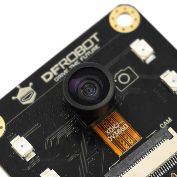
Equipped with a 160° wide-angle infrared camera and infrared illumination, the ESP32-S3 AI CAM ensures exceptional image quality even in low-light or complete darkness. The module’s light sensor further enhances adaptability, making it an ideal choice for 24/7 monitoring in applications like baby monitoring, security surveillance, and smart home systems. Its ability to perform in all weather and lighting conditions makes it a reliable solution for around-the-clock surveillance.

Wireless Transmission Support: Wi-Fi & BLE 5
The ESP32-S3 AI Camera Module is equipped with Wi-Fi and BLE 5 connectivity, enabling seamless remote monitoring from your mobile devices or other connected equipment. Whether you're at home or on the go, you can easily access live video feeds and manage your monitoring system remotely. This wireless transmission capability expands the flexibility of the module, making it an ideal solution for applications requiring real-time surveillance and control, such as home security and smart automation.

Features
- Various AI capabilities
Edge image recognition (based on EdgeImpulse)
Online image recognition (openCV, YOLO)
Online large models for voice and image (ChatGPT) - Equipped with a wide-angle night vision camera, infrared illumination, and all-day usability
- Onboard microphone and amplifier for voice interaction
- Offers a variety of AI models, with tutorial support for quick learning
Applications
- Electronic peepholes
- License plate recognition
- AI Robot Toy
- Smart Glasses

Specification
Basic Parameters
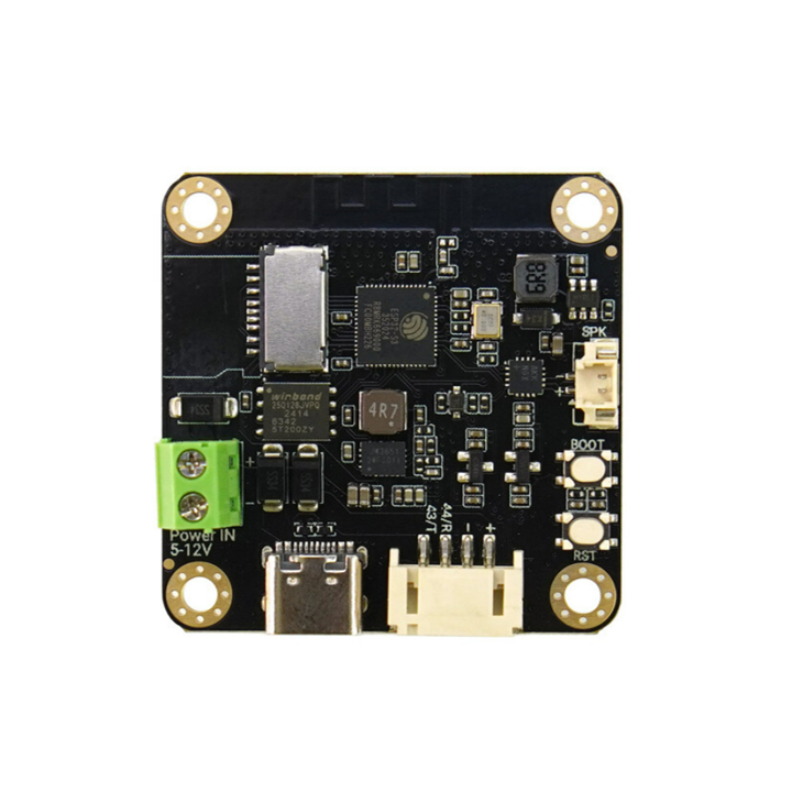
- Operating Voltage: 3.3V
- Type-C Input Voltage: 5V DC
- VIN Input Voltage: 5-12V DC
- Operating Temperature: -10~60°C
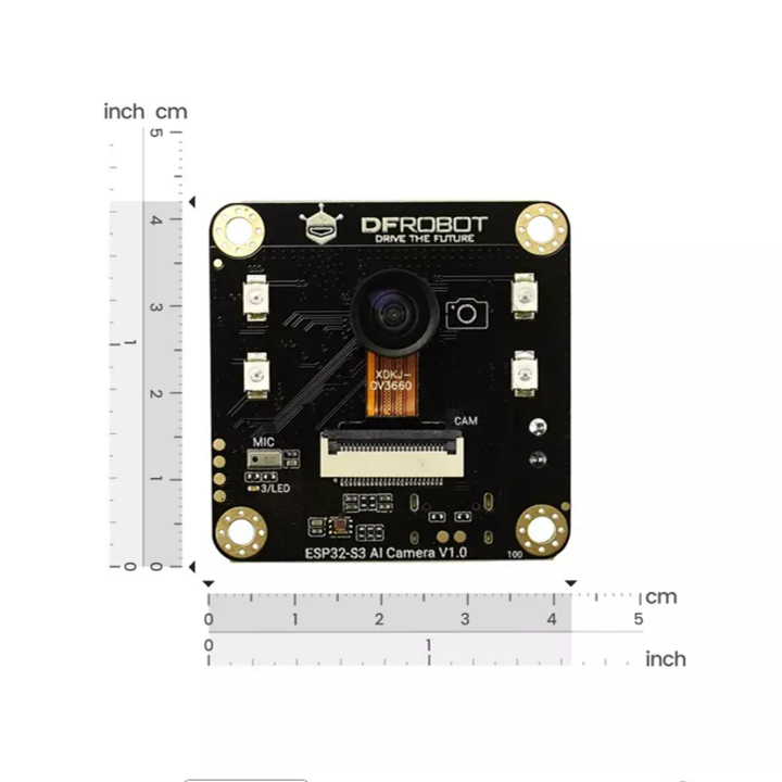
- Module Size: 42*42mm
Functional Indicators

- OV3660: 160° wide-angle infrared camera
- IR: Infrared illumination (IO47)
- MIC: I2S PDM microphone
- LED: Onboard LED (IO3)
- ALS: LTR-308 ambient light sensor
- ESP32-S3: ESP32-S3R8 chip
- SD: SD card slot
- Flash: 16MB Flash
- VIN: 5-12V DC input
- HM6245: Power chip
- Type-C: USB Type-C interface for power and code uploading
- Gravity
+: 3.3-5V
-: GND
44: IO44/TX
43: IO43/RX - RST: Reset button
- BOOT: BOOT button (IO0)
- SPK: MX1.25-2P speaker interface
- MAX98357: I2S amplifier chip
Camera Specifications
- Sensor Model: OV3660
- Pixels: 2 Megapixels
- Sensitivity: Visible light, 940nm infrared
- Field of View: 160°
- Focal Length (EFL): 0.95
- Aperture (F/No.): 2.0±5%
- Distortion: < 8%
Documents
- Product Wiki
- Tutorial - HomeAssistant Integration
- OpenAI Image Q&A Demo Code
- OpenAI Real-Time Communication (RTC) Demo for ESP-IDF (GitHub Repository)
- More Tutorials
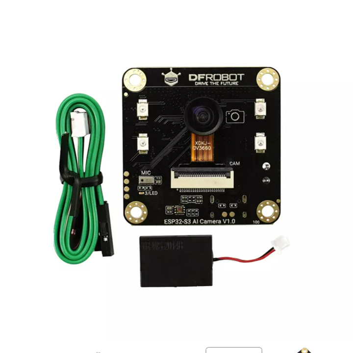
Shipping List
- ESP32-S3 AI CAM development board (with camera) x1
- Speaker x1
- Gravity-4P I2C/UART sensor connection cable x1
Tutorial - First Time Use
Arduino IDE Configuration
Please pay attention to the followings when using ESP32-S3 AI CAM for the first time.
- Add the json link in the IDE
- Download the core of the MCU
- Select the development board and serial port
- Open the sample code and burn it into the board
- Get to know the serial monitor
Arduino IDE compiler environment config
- Configure URL to the Arduino IDE
- Open Arduino IDE and click File->Preferences, as shown below.

- In the newly opened interface, click the button in the red circle as shown below

-
Copy the following link into the new pop-up dialog box:
Stable version:https://espressif.github.io/arduino-esp32/package_esp32_index.json
Development release:https://espressif.github.io/arduino-esp32/package_esp32_dev_index.json
Note:
- Please choose the appropriate version according to Chip Support Situation.
- If you have installed another environment before, you can press Enter key at the beginning or end of the previous link and paste the link at a new line.

- Click OK. Update the board. Open Tools->Board:->Boards Manager... as shown below:

- Boards Manager will automatically update the boards as shown below:

- After completing the update, you can enter esp32 at the top, select esp32 and click install when the following occurs (It's recommended to install the latest version):

- Wait for the end of the following progress bar:

- After completing the installation, the list will show that the esp32 has been installed, as shown below:

-
Click Tools->Board, select "ESP32S3 Dev Module".

-
Before starting, you need to configure the following settings (when you select Disabled, the serial port is RX, TX, if you need to print on the Arduino monitor via USB, you need to select Enable)

- Click Port to select the corresponding serial port.
5.2 LED Blinking
The default pin for the onboard LED is pin 3.
Sample Code
- Copy the codes above to the code editing box.
- Click the arrow to complile the program and burn it into your development board.
Burning Successful

The image above shows that your codes have been successfully loaded into the board. Then, the onboard LED will start blinking.
ESP32 Tutorials
Video Transmission
Steps
- In the Arduino IDE, select File->Examples->ESP32->Camera->CameraWebServer example.
- Replace the code in CameraWebServer with the following code (Note: You need to fill in the WIFI account and password).
- Open the serial monitor to check the IP address.
- Use a device within the local area network to access the IP through a browser, and click "start" to view the surveillance screen.
Recording and Playing Audio
This example demonstrates the recording and playback functionality. After uploading the code and resetting the development board, the LED will light up to indicate a 5-second recording. Once the LED turns off, the recording will play back through the speaker.
OpenAI image Q&A
This example demonstrates the connection of the ESP32-S3 AI CAM to openAI for voice and image recognition.
After flashing the code, press and hold the "boot" button and ask questions to the module, such as "What do you see?", "What kind of plant is this?", "What is he doing?". The module will send the audio and image data to openAI for recognition, and play the recognition results in the form of voice.

OpenAI WebRTC
Through this sample code, you can have a real-time conversation with OpenAI.
Note: This code runs under ESP-IDF.
Object Contour Recognition Using OpenCV on PC
This example demonstrates object contour recognition using OpenCV on a PC.
Steps
- Upload the "CameraWeb" example code to the module and check the IP address.
- Install the Python environment (https://www.python.org/) (if you already have it installed, skip to the next step).
- Install the necessary Python libraries:
- Press Win+R, type "cmd" to enter the command window.
- Enter "pip install numpy" to install the numpy library.
- Enter "pip install opencv-python" to install the opencv-python library.
- Enter "pip install opencv-contrib-python" to install the opencv-contrib-python library.
- Modify the IP address in the fifth line of the
openCV-demo.pyto the IP address of your ESP32-S3. - Open Python's IDLE, go to File -> Open..., select
openCV-demo.py, and press F5 in the new window to see the recognition screen and results.

Object Classification Using YOLOv5 on PC
This example demonstrates object classification using YOLOv5 on a PC.
Steps
- Upload the "CameraWeb" example code to the module and check the IP address.
- Install the Python environment (https://www.python.org/) (if you already have it installed, skip to the next step).
- Install the YOLOv5 library:
- Press Win+R, type "cmd" to enter the command window.
- Enter "pip install numpy" to install the numpy library.
- Enter "pip install yolov5" to install the YOLOv5 library.
- Modify the IP address in the eighth line of the
yoloV5-demo.pyto the IP address of your ESP32-S3. - Open Python's IDLE, go to File -> Open..., select
yoloV5-demo.py, and press F5 in the new window to see the recognition screen and results.

Image Recognition Using EdgeImpulse
This example demonstrates how to implement image recognition on the module using EdgeImpulse.
Note: Different SDK versions may cause compilation errors (demo SDK version 3.0.1).
Steps
- Extract the trained model files to the "arduino->libraries" folder.
- Replace the "depthwise_conv.cpp" and "conv.cpp" files in "src\edge-impulse-sdk\tensorflow\lite\micro\kernels".
- Move the
edge_camerafolder and its subfolders into the examples folder of the model library. - Open the Arduino IDE, select the
edge_cameraexample, modify the first line of the code to match the model library's .h file, enter the WiFi credentials, then compile and upload. - Open the serial monitor to see the IP address and recognition results. Access the IP to view the camera feed.

Training custom models with EdgeImpulse
Access HomeAssistant
Based on this tutorial, you can add the ESP32 - S3 camera module to HomeAssistant and view the monitoring footage.
Access the HomeAssistant tutorial
Retrieving Ambient Light Data
This example allows you to retrieve ambient light data.
Before using, please install the LTR308 Sensor Library
FAQ
-
Q:What protocol does the MIC use?
A:The MIC uses the PDM protocol. For more parameters of the MIC, please refer to the datasheet: https://dfimg.dfrobot.com/5d57611a3416442fa39bffca/wiki/d2c58ceeebf0ab6a527b0c37c0ef525e.pdf -
Q:What is the specification of the speaker interface? What parameters of speaker are supported?
A:The speaker interface uses an MX1.25mm interface, and the recommended speaker parameters are 4R1.5W and 8R1W. -
Q:Can the EdgeImpulse object classification model be customized?
A:Yes, it is supported. Please refer to the training method at: https://wiki.dfrobot.com/EdgeImpulse_Object_Detection -
Q:What are the parameters of the infrared fill light?
A:The maximum power of a single LED is 75mW, the minimum radiation intensity is 5mW/sr, and the standard radiation intensity is 7mW/sr. -
Q:What is the maximum supported size of TF card?
A:The maximum supported size is 32GB FAT32 formatted TF card.
Related Documents
- openAIImageQA Demo
- openAI RTC Demo for ESP-IDF
- EdgeImpulse Demo
- openCV Demo
- yoloV5 Demo
- Schematic
- Dimension Drawing
- OV3660 Specifications
- OV3660 Datasheet
- MIC Datasheet
วิธีการชำระเงิน
ชำระเงินค่าสินค้าโดยการโอนเงินเข้าบัญชีธนาคาร KBANK, SCB, BBL,TMB
กรุณาเก็บหลักฐานการโอนเงินของท่านไว้เพื่อแจ้งการชำระเงินด้วยค่ะ
ท่านสามารถแจ้งการชำระเงินผ่านระบบอัตโนมัติได้โดย Click Link ข้างล่างค่ะ
https://www.arduitronics.com/informpayment
ชำระเงินผ่านธนาคาร


@rfm0967y
ติดต่อสอบถาม
Join เป็นสมาชิกร้านค้า
MEMBER
