
RS485 Waterproof Ambient Light Sensor (0-200,000 Lux) แท้จาก DFRobot
| รหัสสินค้า | AS00635 |
| หมวดหมู่ | วัดสภาพแวดล้อมและแก๊ส Environmental / Gas |
| ราคา | 625.00 บาท |

รายละเอียดสินค้า
Introduction
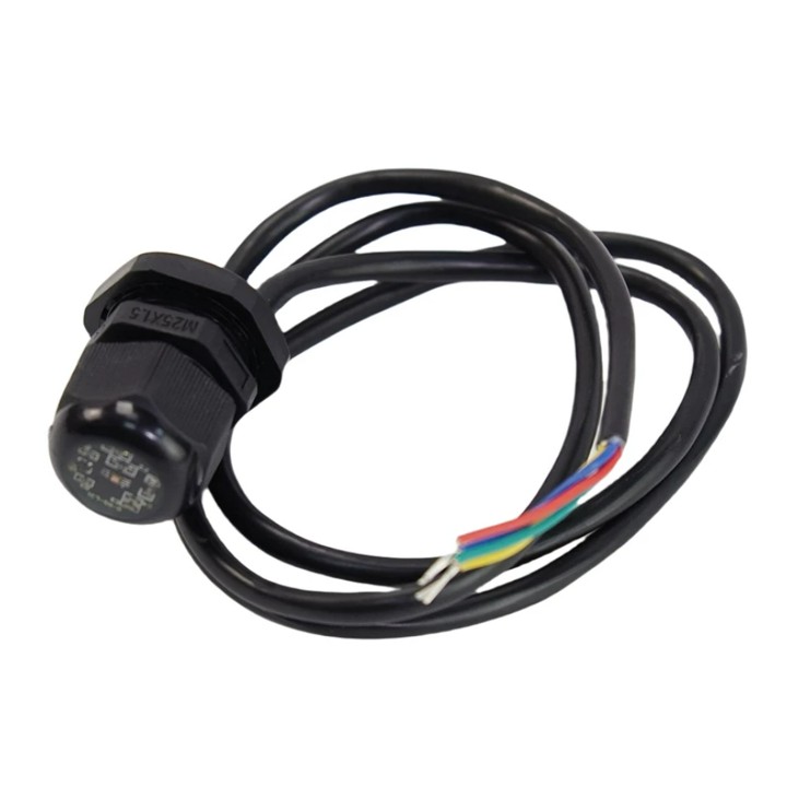
The Waterproof Digital Ambient Light Sensor is a robust and versatile device designed to measure light intensity across a wide range of environments, from 0 to 200,000 Lux. Utilizing the Modbus-RTU 485 communication protocol and powered by a DC 5-32V wide voltage supply, it ensures seamless integration with systems like the Arduino via compatible expansion boards.
With an IP68 waterproof rating, the sensor can withstand complete submersion, making it ideal for both indoor and outdoor applications, including weather stations, greenhouses, outdoor lighting, and automotive smart lights. Its high accuracy (±5%), broad measurement range, and durable construction make it a reliable solution for demanding environments.
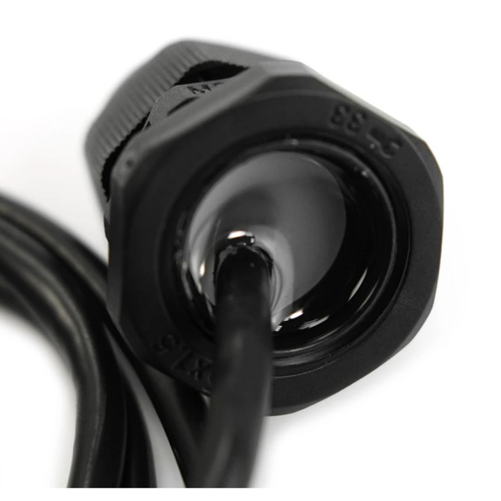
IP68 Waterproof Design
The sensor is fully waterproof, meeting the IP68 standard, and can be submerged in water without damage. This makes it suitable for use in harsh outdoor environments, such as weather stations, greenhouses, and automotive applications, ensuring consistent performance in wet or humid conditions.
Wide Range and High Accuracy
With a measurement range of 0-200,000 Lux and a resolution of 0.01 Lux, the sensor provides precise light intensity readings across diverse scenarios, from dim indoor settings to bright outdoor environments. Its ±5% accuracy ensures reliable data for critical applications like plant growth monitoring and lighting control.
Easy Integration and Compatibility
The sensor supports the Modbus-RTU 485 protocol and can be easily connected to Arduino and other microcontroller platforms using expansion boards like the TTL to RS485 module or the Gravity: Active Isolated RS485 to UART Signal Adapter. Its simple wiring and wide voltage power supply (DC 5-32V) make it user-friendly and adaptable to various setups.
Applications
- Weather Stations: Monitor ambient light for accurate weather data collection.
- Greenhouses: Optimize plant growth by measuring light intensity in vegetable and flower cultivation.
- Outdoor Lighting: Automate streetlights or garden lighting based on ambient light levels.
- Automotive Smart Lights: Enhance vehicle safety with adaptive lighting systems.
- Factory Lighting: Ensure optimal lighting conditions in industrial workshops.
Specification
- Power supply voltage: DC 5-32V
- Working current: <10mA
- Output mode: RS485
- Measurement range: 0-200,000 Lux
- Resolution: 0.01 Lux
- Accuracy: ±5%
- Working temperature: -40°C~+80°C
- Protection level: IP68
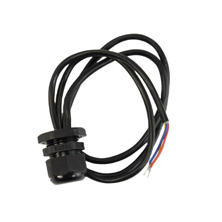
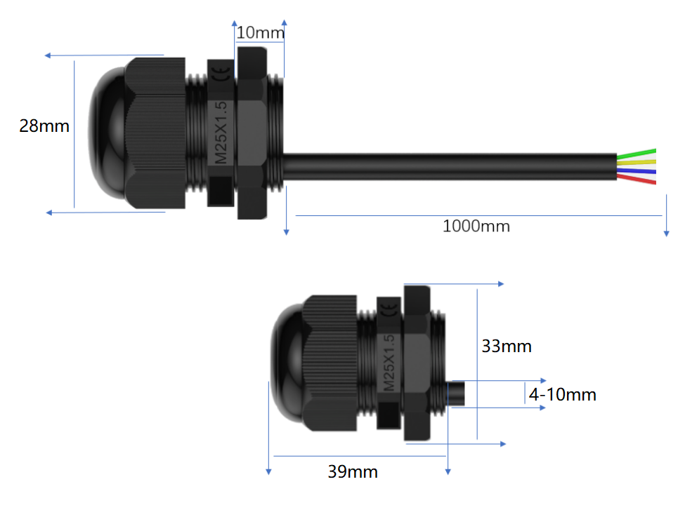
- Thread length: 10mm
- Opening size: 25mm
- Wrench size: 33mm
- Cable diameter: 4-10mm
- Line length: 1m
Documents
Shipping List
- RS485 Waterproof Ambient Light Sensor (0-200,000 Lux) x1
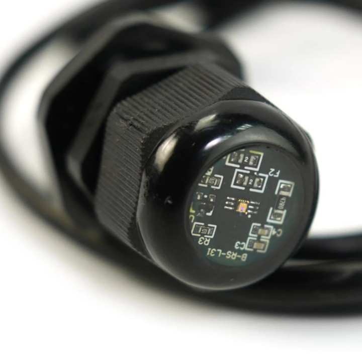
Board Overview
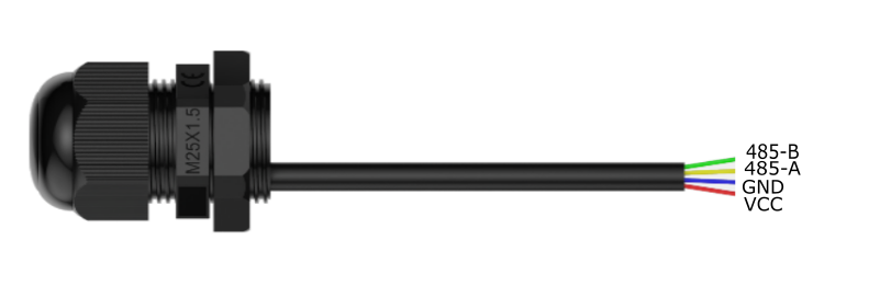
| Num | Label | Description |
|---|---|---|
| Red line | VCC | Power input positive pole, DC5-32V power supply |
| Blue line | GND | Power ground wire |
| Yellow line | 485-A | RS485 data line A |
| Green line | 485-B | RS485 data line B |
Dimensional Drawing
Communication Protocol
1. Basic communication parameters
| Interface | Encoding | Data bits | Parity bits | Stop bits | Error checking | Baud rate |
|---|---|---|---|---|---|---|
| RS485 | 8-bit binary | 8 | None | 1 | CRC | 1200、2400、4800、9600、19200、38400、57600 bit/s configurable, default 9600bit/s |
2. Data frame format definition
Using Modbus-RTU communication protocol, the format is as follows:
Initial structure ≥4 bytes of time
Address code = 1 byte
Function code = 1 byte
Data area = N bytes
Error check = 16-bit CRC code
End structure ≥4 bytes of time
Address code: The address of the sensor, which is unique in the communication network (factory default 0x01).
Function code: The function indication of the command sent by the host. This sensor reads the register function code 0x03 and writes the register function code 0x06
Data area: The data area is the specific communication data. Note that the high byte of 16-bit data is in front!
CRC code: A two-byte check code.
Register address
| Register address | Content | Operation | Range and definition |
|---|---|---|---|
| 0002H | High 16-bit data of illumination value | Read-only | Two bytes |
| 0003H | Low 16-bit data of illumination value | Read-only | Two bytes |
| 0046H | Illumination acquisition rate | Read-write | Level 1-20 |
| 0047H | Illumination calibration enable bit | Read-write | 01 Enable illumination calibration function, 00 Disable illumination calibration function |
| 0048H | Illumination calibration compensation value | Read-write | This value is written with the actual value enlarged by 100 times; for example, if compensation of 1.4 is required, the written value needs to be enlarged by 100 times, that is, 140; Calculation method: (collected illumination value ÷ ambient illumination value) × 100 = compensation value For example: the collected illumination value is 221, the actual ambient illumination is 260, and the calculated compensation value = (221 ÷ 260) × 100 = 85 |
| 0064H | 16-bit device address | Read and write | Range is (1-254), 255 is the general control command address |
| 0065H | 16-bit baud rate selection | Read and write | 0-1200, 1-2400, 2-4800, 3-9600, 4-19200, 5-38400, 6-57600 |
| 0066H | Parity bit | Read and write | 00 no parity, 01 odd parity, 02 even parity |
| 0067H | Version information | Read only | Level 1-20 |
| 00E0H | Device soft reset write command | Write only | Level 1-20 |
| 00F0H | Device factory reset write command | Write only | Level 1-20 |
3. Communication protocol example and explanation
3.1、Read multiple register illumination data instruction
Inquiry frame:
| Address code | Function code | Register start address | Register length | Check code low bit | Check code high bit |
|---|---|---|---|---|---|
| 0x01 | 0x03 | 0x00 0x02 | 0x00 0x02 | 0x65 | 0xCB |
Response frame:
| Address code | Function code | Return valid bytes | Illumination data high 16 bits | Illumination data low 16 bits | Check code low bit | Check code high bit |
|---|---|---|---|---|---|---|
| 0x01 | 0x03 | 0x04 | 0x00 0x0C | 0xF4 0x73 | 0x3D | 0x15 |
Light value:
00 0C F4 73 (hexadecimal) =849011/1000 =>Light value = 849.011Lux
3.2, Modify the current address
Inquiry frame: (Modify the current address to 0x02)
| Address code | Function code | Register address | Modify value | Check code low bit | Check code high bit |
|---|---|---|---|---|---|
| 0x01 | 0x06 | 0x00 0x64 | 0x00 0x02 | 0x49 | 0xD4 |
Response frame:
| Address code | Function code | Register address | Modify value | Checksum low bit | Checksum high bit |
|---|---|---|---|---|---|
| 0x01 | 0x06 | 0x00 0x64 | 0x00 0x02 | 0x49 | 0xD4 |
3.3, Modify address, baud rate
Inquiry frame: (Modify address to 0x01, baud rate to 9600)
After modifying the address or baud rate, the sensor needs to be powered off and reconnected
| Address code | Function code | Register start address | Register length | Modify address | Modify baud rate | Parity check | Checksum low bit | Checksum high bit |
|---|---|---|---|---|---|---|---|---|
| 0x01 | 0x10 | 0x00 0x64 | 0x00 0x03 | 0x00 0x01 | 0x00 0x03 | 0x00 0x00 | 0xA9 | 0x03 |
Response frame:
| Address code | Function code | Register start address | Register length | Modify address | Modify baud rate | Checksum low bit | Checksum high bit |
|---|---|---|---|---|---|---|---|
| 0x01 | 0x10 | 0x00 0x64 | 0x00 0x03 | 0x00 0x01 | 0x00 0x03 | 0x9C | 0x05 |
3.4, query current address, baud rate
Inquiry frame:
| Address code | Function code | Register start address | Data length | Check code low bit | Check code high bit |
|---|---|---|---|---|---|
| 0xFF | 0x03 | 0x00 0x64 | 0x00 0x02 | 0x90 | 0x0A |
Response frame:
| Address code | Function code | Return valid bytes | Device address | Baud rate | Check code low bit | Check code high bit |
|---|---|---|---|---|---|---|
| 0x01 | 0x03 | 0x04 | 0x00 0x01 | 0x00 0x03 | 0xEB | 0xF2 |
The real address of the device read is 01, and the baud rate is 0x03, which is 9600.
3.5, Device factory reset command
Inquiry frame:
| Address code | Function code | Register address | Modify data | Check code low | Check code high |
|---|---|---|---|---|---|
| 0xFF | 0x06 | 0x00 0xF0 | 0x00 0x00 | 0x9C | 0x27 |
Response frame:
| Address code | Function code | Register address | Modify data | Check code low | Check code high |
|---|---|---|---|---|---|
| 0xFF | 0x06 | 0x00 0xF0 | 0x00 0x00 | 0x9C | 0x27 |
Tutorial
Requirements
- Hardware
- DFRduino UNO R3 (or similar) x 1
- Gravity: Active Isolated RS485 to UART Signal Adapter Module x1
- RS485 Waterproof Ambient Light Sensor(0-200klux) x1
- Software
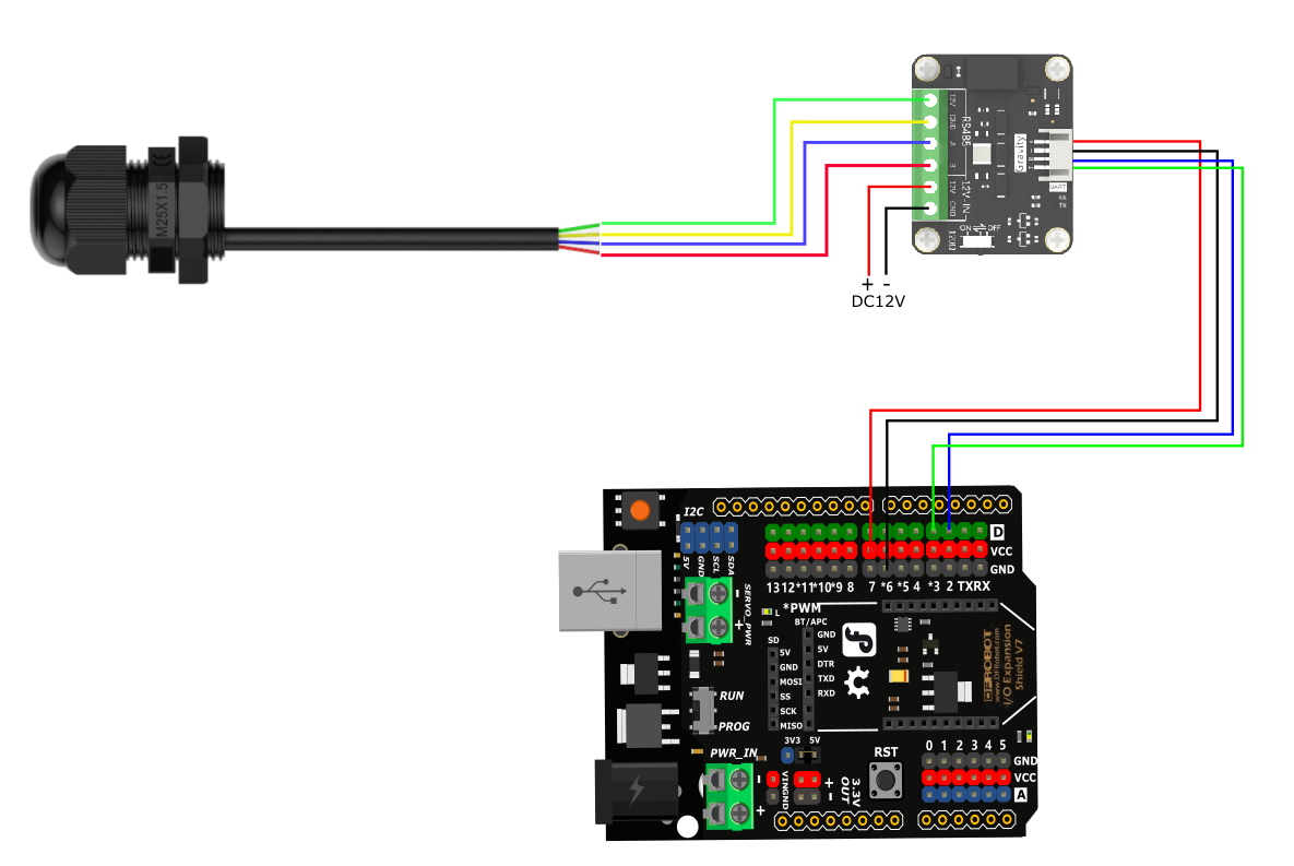
Connection Diagram
If the power of the RS485 device is small and the required current is less than 12V-160mA, the RS485 to UART signal conversion module does not require a 12V external power supply, making wiring more convenient.
Sample Code
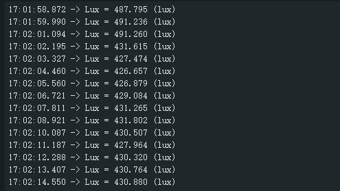
Expected Results
Print the collected light values
FAQ
Possible reasons for no output or output errors:
- The sensor is a precision device. Please do not disassemble it by yourself when using it to avoid damage to the product.
- If the reading value is 0, check whether there is a light source and whether the product protective cover is removed.
- The 485 bus is disconnected, or the A and B lines are connected in reverse.
- Check whether the power supply meets the marking.
วิธีการชำระเงิน
ชำระเงินค่าสินค้าโดยการโอนเงินเข้าบัญชีธนาคาร KBANK, SCB, BBL,TMB
กรุณาเก็บหลักฐานการโอนเงินของท่านไว้เพื่อแจ้งการชำระเงินด้วยค่ะ
ท่านสามารถแจ้งการชำระเงินผ่านระบบอัตโนมัติได้โดย Click Link ข้างล่างค่ะ
https://www.arduitronics.com/informpayment
ชำระเงินผ่านธนาคาร


@rfm0967y
ติดต่อสอบถาม
Join เป็นสมาชิกร้านค้า
MEMBER
