
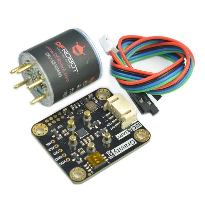
Gravity: NH3 Sensor (Calibrated) - I2C & UART - แท้ DFRobot
| รหัสสินค้า | AS00628 |
| หมวดหมู่ | Gas Sensors แก๊สเซ็นเซอร์ |
| ราคา | 5,450.00 บาท |
| สถานะสินค้า | พร้อมส่ง |
| จำนวน | ชิ้น |

รายละเอียดสินค้า
ดูการใช้งานอย่างละเอียดและตัวอย่าง code ได้ที่ Product WiKi
Introduction
Features
- Strong anti-interference ability
- High stability
- High sensitivity
Applications
- Industrial ammonia detection
- Environmental protection device
Specification
- Detection Gas: Ammonia (NH3)
- Detection range: 0~100ppm
- Working Voltage: 3.3~5.5V DC
- Working Current: < 5mA
- Output Signal: I2C, UART (0~3V), analog voltage
- Working Temperature: -20~50℃
- Working Humidity: 15~90%RH (non-condensing)
- Storage Temperature: -20~50℃
- Storage Humidity: 15~90%RH (non-condensing)
- Lifespan: > 2 years (in the air)
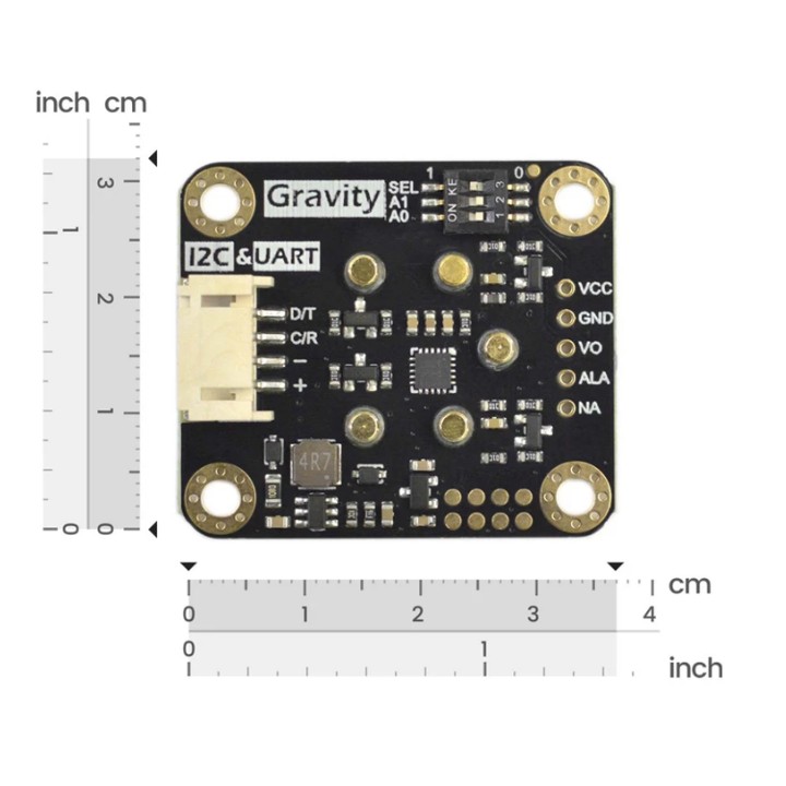
- Adapter Plate Size: 37*32mm
- Compatibility: Arduino, ESP32, Raspberry pi
Projects
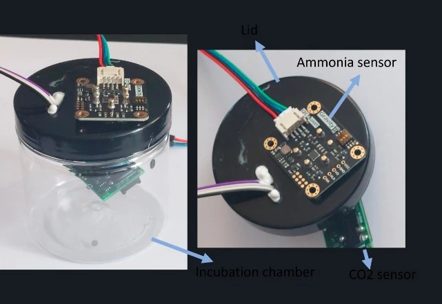
Project: Accurate soil health assessment using calibrated ammonia gas sensors
Documents
Shipping List
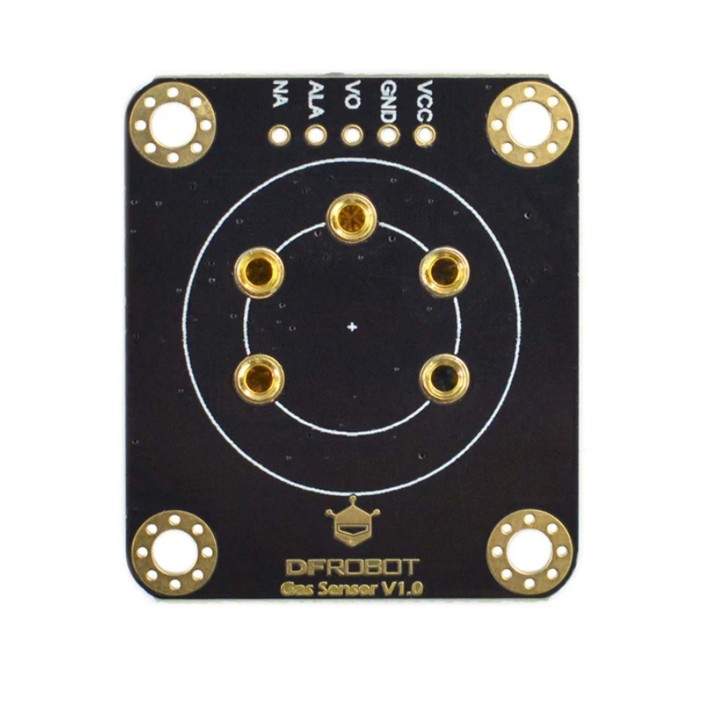
- Gravity: NH3 Signal Conversion Board x1
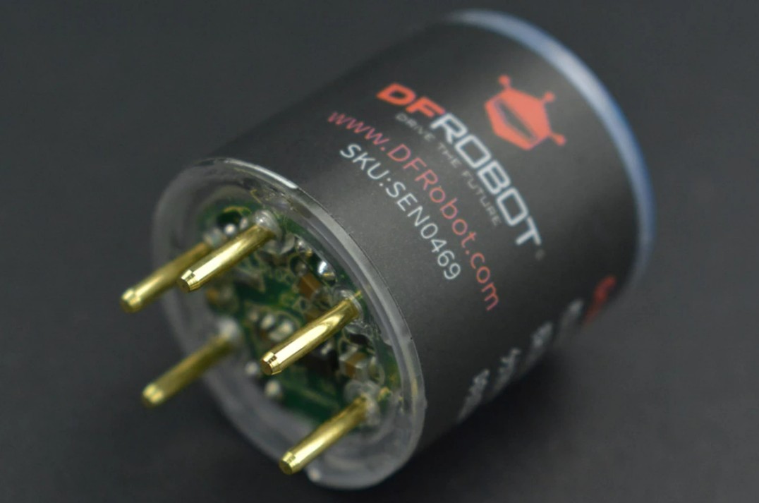
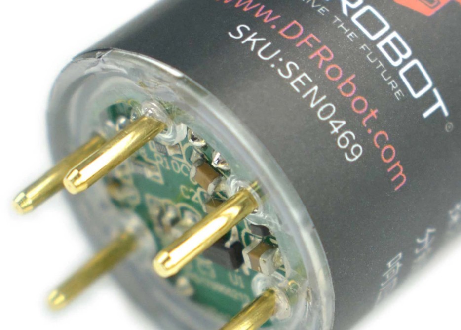
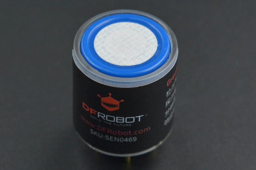
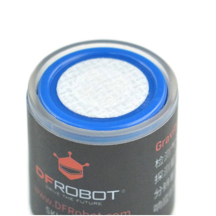
- NH3 sensor probe x1
- Gravity - 4pin Cable x1
Tutorial for Arduino
Download the program to UNO and open the serial monitor to check the gas concentration.
Note:
- The initial power-on requires more than 5 minutes of preheating. It is recommended to preheat more than 24 hours if it has not been used for a long time.
- After switching the communication mode or changing the I2C address, the system needs to be powered off and on again.
Requirements
-
Hardware
- DFRuino UNO R3 x1
- DFR0784 Smart Gas Sensor Terminal x1
- Gas probe x1
- Jumper wires
-
Software
- Arduino IDE
- Download and install the DFRobot_GasSensor Library (About how to install the library?)
Acquire data in passive mode
Connection

Sample code
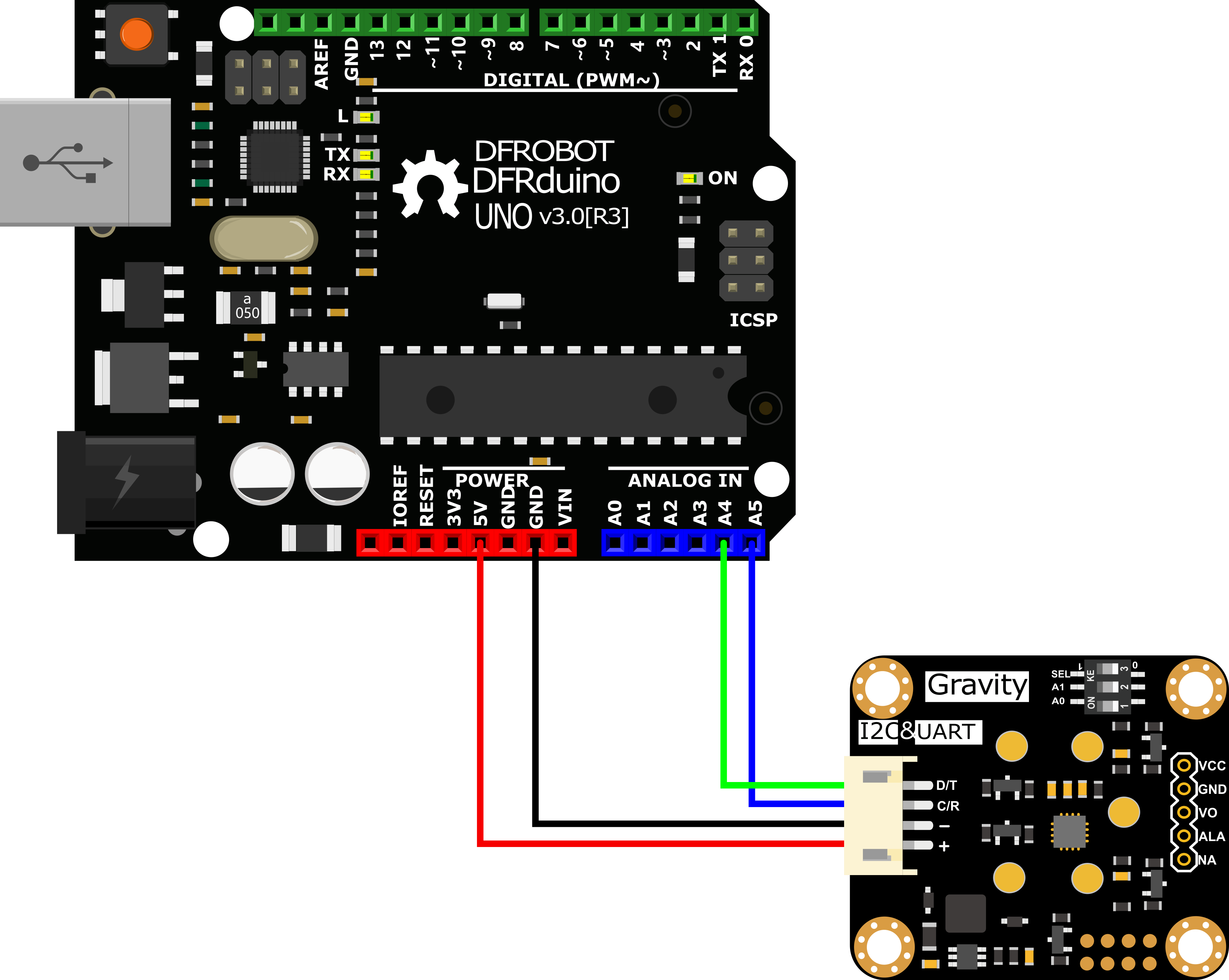
- Connect the module to the Arduino according to the connection diagram above. Of course, you can also use it with Gravity I/O Expansion Board to build the project prototype more conveniently and quickly.
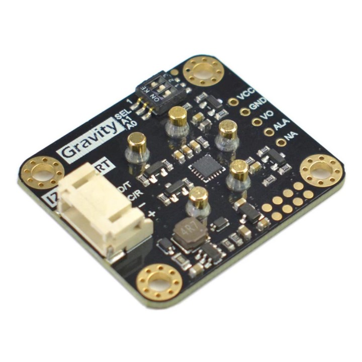
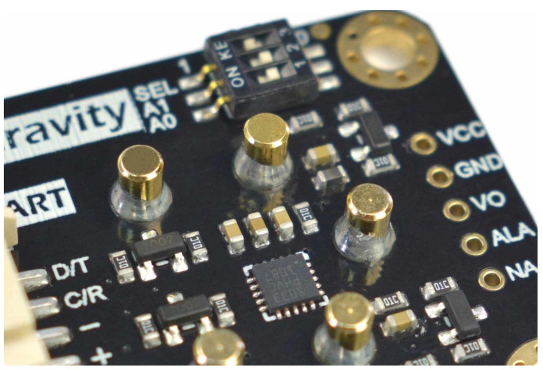
- Set the DIP switch SEL on the sensor to 0, and use I2C communication by default.
- The default I2C address is 0x74. If you need to modify the I2C address,You can configure the hardware I2C address through the DIP switch on the module, or run the code to modify the address group to modify the address. The corresponding relationship between the DIP switch and the I2C address parameter is as follows:
- ADDRESS_0: 0x74, A0=0, A1=0
- ADDRESS_1: 0x75, A0=0, A1=1
- ADDRESS_2: 0x76, A0=1, A1=0
- ADDRESS_3: 0x77, A0=1, A1=1
- Download and install the DFRobot_GasSensor Library (About how to install the library?)
- Open Arduino IDE and upload the following code to Arduino UNO.
- Open the serial port monitor of Arduino IDE, adjust the baud rate to 115200, and observe the serial port print result.
Statement
- In this routine, the controller needs to request data from the sensor every time, and then the sensor returns the data.
- Default use I2C communication, mask
#define I2C_COMMUNICATIONin the code, and set the dip switch SEL to 1, the sensor is connected to the corresponding port defined by the controller, if use UNO, the blue line is connected to D3 and the green line is connected to D2, if use ESP32, the blue line is connected to IO17 and the green line is connected to IO16. After re-uploading the code, the whole system will be re-powered and will switch to UART communication. - Turn off temperature compensation by default, modify the code
gas.setTempCompensation(gas.ON);, turn on temperature compensation after re-uploading the code
Result
Open the serial monitor to get the gas type, concentration and temperature.
- The initial power-on requires more than 5 minutes of preheating. It is recommended to preheat more than 24 hours if it has not been used for a long time.
- After switching the communication mode and changing the I2C address, the system needs to be powered off and on again.

Acquire data in initiative mode
Connection
-
Sample code
-
Connect the module to the Arduino according to the connection diagram above. Of course, you can also use it with Gravity I/O Expansion Board to build the project prototype more conveniently and quickly.
-
Set the DIP switch SEL on the sensor to 0, and use I2C communication by default.
-
The default I2C address is 0x74. If you need to modify the I2C address,You can configure the hardware I2C address through the DIP switch on the module, or run the code to modify the address group to modify the address. The corresponding relationship between the DIP switch and the I2C address parameter is as follows:
- ADDRESS_0: 0x74, A0=0, A1=0
- ADDRESS_1: 0x75, A0=0, A1=1
- ADDRESS_2: 0x76, A0=1, A1=0
- ADDRESS_3: 0x77, A0=1, A1=1
-
Download and install the DFRobot_GasSensor Library (About how to install the library?)
-
Open Arduino IDE and upload the following code to Arduino UNO.
-
Open the serial port monitor of Arduino IDE, adjust the baud rate to 115200, and observe the serial port print result.
Statement
- In this routine, the sensor will actively return data once a second, and the controller will receive and parse the data.
-
Default use I2C communication, mask `#define I2C_COMMUNICATION in the code, and set the dip switch SEL to 1, the sensor is connected to the corresponding port defined by the controller, if use UNO, the blue line is connected to D3 and the green line is connected to D2, if use ESP32, the blue line is connected to IO17 and the green line is connected to IO16. After re-uploading the code, the whole system will be re-powered and will switch to UART communication.
-
Turn off temperature compensation by default, modify the code
gas.setTempCompensation(gas.ON);, turn on temperature compensation after re-uploading the code
Result
Open the serial monitor, then you can get the corresponding gas concentration.
-
The initial power-on requires more than 5 minutes of preheating. It is recommended to preheat more than 24 hours if it has not been used for a long time.
-
After switching the communication mode and changing the I2C address, the system needs to be powered off and on again.

Threshold alarm function
Connection

-
Sample code
-
Connect the module to the Arduino according to the connection diagram above. Of course, you can also use it with Gravity I/O Expansion Board to build the project prototype more conveniently and quickly.
-
Set the DIP switch SEL on the sensor to 0, and use I2C communication by default.
-
The default I2C address is 0x74. If you need to modify the I2C address,You can configure the hardware I2C address through the DIP switch on the module, or run the code to modify the address group to modify the address. The corresponding relationship between the DIP switch and the I2C address parameter is as follows:
- ADDRESS_0: 0x74, A0=0, A1=0
- ADDRESS_1: 0x75, A0=0, A1=1
- ADDRESS_2: 0x76, A0=1, A1=0
- ADDRESS_3: 0x77, A0=1, A1=1
-
Download and install the DFRobot_GasSensor Library (About how to install the library?)
-
Open Arduino IDE and upload the following code to Arduino UNO.
-
Open the serial port monitor of Arduino IDE, adjust the baud rate to 115200, and observe the serial port print result.
Result
-*After uploading the code successfully, open the serial monitor and you can observe the alarm message. *
-ALA outputs low level by default when no alarm is triggered. Modify the HIGH_THRESHOLD_ALA parameter in the gas.setThresholdAlarm function to LOW_THRESHOLD_ALA, then ALA outputs high level when no alarm is triggered

API description
DFR0784 Gravity: Electrochemical Smart Gas Sensor Terminal There are two data reading modes: active upload and passive response. The factory default is active upload mode, and users can adjust them in the code according to their needs.
Mode selection function "changeAcquireMode()"
Modify the parameters in brackets of the "changeAcquireMode()" function to adjust the data sending mode.
"INITIATIVE" is the active upload mode. In the active upload mode, the sensor will automatically upload parameters every 1 second;
"PASSIVITY" is the passive response mode. In the passive response mode, the sensor will feedback the parameters only every time the data reading function is called.
Set the probe type function "setGasType()"
Set the probe type by the "setGasType()" function.
Read the probe type function "queryGasType()"
Through the "queryGasType()" function, You can get the type of current gas probe.
For probe compatible types and corresponding parameters, please refer to the table below.
| Gas type | CO | O2 | NH3 | H2S | NO2 | HCL |
|---|---|---|---|---|---|---|
| Detection range | (0-1000)ppm | (0-25)%VOL | (0-100)ppm | (0-100)ppm | (0-20)ppm | (0-10)ppm |
| Resolution | 1ppm | 0.1%VOL | 1ppm | 1ppm | 0.1ppm | 0.1ppm |
| V0 voltage output range | (0.6-3)V | (1.5-0)V | (0.6-3)V | (0.6-3)V | (2-0)V | (2-0)V |
| Response time (T90) | ≤30S | ≤15S | ≤150S | ≤30S | ≤30S | ≤60S |
| Gas type | H2 | PH3 | SO2 | O3 | CL2 | HF |
|---|---|---|---|---|---|---|
| Detection range | (0-1000)ppm | (0-1000)ppm | (0-20)ppm | (0-10)ppm | (0-20)ppm | (0-10)ppm |
| Resolution | 1ppm | 0.1ppm | 0.1ppm | 0.1ppm | 0.1ppm | 0.1ppm |
| V0 voltage output range | (0.6-3)V | (0.6-3)V | (0.6-3)V | (2-0)V | (2-0)V | (2-0)V |
| Response time (T90) | ≤120S | ≤30S | ≤30S | ≤120S | ≤60S | ≤60S |
Gas concentration reading function "readGasConcentrationPPM()"
The feedback gas concentration value of the gas sensor can be read through the "readGasConcentrationPPM()" function.
Temperature reading function "readTempC()"
The onboard temperature sensor data can be read through the "readTempC()" function.
Voltage reading function "getSensorVoltage()"
The original voltage output V0 of the gas probe can be read through the "getSensorVoltage()" function.
Configure temperature compensation function "setTempCompensation()"
You can enable/disable the temperature compensation function through the "setTempCompensation()" function.
Threshold alarm function "setThresholdAlarm()"
You can configure the threshold alarm information through the "setThresholdAlarm()" function
I2C address group configuration function "changeI2cAddrGroup()"
You can configure the I2C address group code and switch between different address groups through the "changeI2cAddrGroup()" function.
In order to prevent address conflicts when using multiple sensors, we have prepared 8 groups with a total of 23 addresses. If necessary, You can use "change_sensor_iic_addr.ino" in the library file "example",to switch by modifying the group serial number configuration of "changeI2cAddrGroup()". After the serial port information displays "IIC addr change success!", power on again.
Serial port protocol usage tutorial
Through the UART serial communication protocol, you can connect DFR0784 Gravity: Electrochemical Smart Gas Sensor Terminal to any controller with UART for data reading and sensor configuration. Note: At this time, the SEL end of the DIP switch on the sensor must be placed in the "1" position
Serial port parameter setting
| Baud rate | 9600 |
|---|---|
| Data bit | 8 bit |
| Check bit | 1 bit |
Communication protocol description

① 0x78——Modify terminal communication mode
The terminal has two communication modes, active uploading and question and answer. The factory default is active uploading mode, and data is sent every 1s.
Send
| Byte0 | Byte1 | Byte2 | Byte3 | Byte4 | Byte5 | Byte6 | Byte7 | Byte8 |
|---|---|---|---|---|---|---|---|---|
| Start bit | addr | Command | Communication mode | -- | -- | -- | -- | Check value |
| 0xFF | 0x01 | 0x78 | Active upload mode: 0x03 Question and answer mode: 0x04 |
0x00 | 0x00 | 0x00 | 0x00 | 0x84 0x83 |
EXP.FF 01 78 03 00 00 00 00 84 (switch to initiative mode)
EXP.FF 01 78 04 00 00 00 00 83 (switch to passive mode)
Return
| Byte0 | Byte1 | Byte2 | Byte3 | Byte4 | Byte5 | Byte6 | Byte7 | Byte8 |
|---|---|---|---|---|---|---|---|---|
| Start bit | Command | Back to calibration | -- | -- | -- | -- | -- | Check value |
| 0xFF | 0x78 | Success: 0x01 Failure: 0x00 |
0x00 | 0x00 | 0x00 | 0x00 | 0x00 | 0x87 0x88 |
EXP.FF 78 01 00 00 00 00 00 87
② Initiative mode,Data Format
In the active upload mode, the terminal will return data every 1s. The data format is as follows.
Return
| Byte0 | Byte1 | Byte2 | Byte3 | Byte4 | Byte5 | Byte6 | Byte7 | Byte8 |
|---|---|---|---|---|---|---|---|---|
| Start bit | Command | Gas concentration high bit |
Gas concentration low bit |
Gas type | Decimal places | Temperature value High |
Temperature value lower |
Check value |
| 0xFF | 0x88 | 0x00 | 0x00 | 0x00 | 0x00 | 0x00 | 0x00 | -- |
Note:
- Gas concentration value = (high gas concentration x 256 + low gas concentration) x resolution
- The decimal place is 0, the resolution is 1; the decimal place is 1, the resolution is 0.1; the decimal place is 2, the resolution is 0.01
- For the calculation method of temperature value, please refer to the sample code below: "Calculation of temperature value"
Gas Type Table
| Gas Type | Command | Gas Type | Command |
|---|---|---|---|
| NH3 | 0x02 | SO2 | 0x2B |
| H2S | 0x03 | NO2 | 0x2C |
| CO | 0x04 | HCL | 0x2E |
| O2 | 0x05 | CL2 | 0X31 |
| H2 | 0x06 | HF | 0x33 |
| O3 | 0x2A | PH3 | 0x45 |
③ 0x86——Passive mode,Read gas concentration data
In the question and answer mode, you need to send commands to read various parameters of the terminal. The method of reading the gas concentration is as follows.
Send
| Byte0 | Byte1 | Byte2 | Byte3 | Byte4 | Byte5 | Byte6 | Byte7 | Byte8 |
|---|---|---|---|---|---|---|---|---|
| Start bit | addr | Command | -- | -- | -- | -- | -- | Check value |
| 0xFF | 0x01 | 0x86 | 0x00 | 0x00 | 0x00 | 0x00 | 0x00 | 0x79 |
EXP.FF 01 86 00 00 00 00 00 79
Return
| Byte0 | Byte1 | Byte2 | Byte3 | Byte4 | Byte5 | Byte6 | Byte7 | Byte8 |
|---|---|---|---|---|---|---|---|---|
| Start bit | Command | Gas concentration high bit |
Gas concentration low bit |
Gas type | Decimal places | -- | -- | Check value |
| 0xFF | 0x86 | 0x00 | 0x00 | 0x00 | 0x00 | 0x00 | 0x00 | 0x7A |
EXP.FF 86 00 00 00 00 00 00 7A
Note:
- Gas concentration value = (high gas concentration x 256 + low gas concentration) x resolution
- The decimal place is 0, the resolution is 1; the decimal place is 1, the resolution is 0.1; the decimal place is 2, the resolution is 0.01
④ 0x87——Passive mode,Read temperature data
In the question and answer mode, you need to read various parameters of the terminal by sending commands. The terminal integrates the thermistor, which can obtain the real-time temperature of the terminal. The way to read the terminal temperature is as follows.
Send
| Byte0 | Byte1 | Byte2 | Byte3 | Byte4 | Byte5 | Byte6 | Byte7 | Byte8 |
|---|---|---|---|---|---|---|---|---|
| Start bit | addr | Command | -- | -- | -- | -- | -- | Check value |
| 0xFF | 0x01 | 0x87 | 0x00 | 0x00 | 0x00 | 0x00 | 0x00 | 0x78 |
EXP.FF 01 87 00 00 00 00 00 78
Return
| Byte0 | Byte1 | Byte2 | Byte3 | Byte4 | Byte5 | Byte6 | Byte7 | Byte8 |
|---|---|---|---|---|---|---|---|---|
| Start bit | Command | Temperature data high bit |
Temperature data low bit |
-- | -- | -- | -- | Check value |
| 0xFF | 0x87 | 0x00 | 0x00 | 0x00 | 0x00 | 0x00 | 0x00 | 0x79 |
EXP.FF 87 00 00 00 00 00 00 79
Note:
For the calculation method of temperature value, please refer to the sample code below: "Calculation of temperature value"
⑤ 0x88——Passive mode,Read temperature and gas concentration data
In the question and answer mode, you need to read various parameters of the terminal by sending commands, and the way to read the temperature and gas concentration data of the terminal is as follows.
Send
| Byte0 | Byte1 | Byte2 | Byte3 | Byte4 | Byte5 | Byte6 | Byte7 | Byte8 |
|---|---|---|---|---|---|---|---|---|
| Start bit | addr | Command | -- | -- | -- | -- | -- | Check value |
| 0xFF | 0x01 | 0x88 | 0x00 | 0x00 | 0x00 | 0x00 | 0x00 | 0x77 |
EXP.FF 01 88 00 00 00 00 00 77
Return
| Byte0 | Byte1 | Byte2 | Byte3 | Byte4 | Byte5 | Byte6 | Byte7 | Byte8 |
|---|---|---|---|---|---|---|---|---|
| Start bit | Command | Gas concentration high bit |
Gas concentration low bit |
Gas type | Decimal places | Temperature value High |
Temperature value lower |
Check value |
| 0xFF | 0x88 | 0x00 | 0x00 | 0x00 | 0x00 | 0x00 | 0x00 | 0x78 |
EXP. FF 88 00 00 00 00 00 00 78
Note:
- Gas concentration value = (high gas concentration x 256 + low gas concentration) x resolution
- The decimal place is 0, the resolution is 1; the decimal place is 1, the resolution is 0.1; the decimal place is 2, the resolution is 0.01
- For the calculation method of temperature value, please refer to the sample code below: "Calculation of temperature value"
⑥ 0x89——Configure threshold alarm function
The terminal has a threshold alarm function, the alarm threshold and judgment logic can be configured. The configuration method is as follows,After the configuration is successful, the entire system needs to be powered on again to take effect.
Note: When no external controller is connected and only the sensor is used to achieve this function, the sensor must be set to active upload mode after the parameters related to the threshold alarm function are configured.
Send
| Byte0 | Byte1 | Byte2 | Byte3 | Byte4 | Byte5 | Byte6 | Byte7 | Byte8 |
|---|---|---|---|---|---|---|---|---|
| Start bit | Empty | Command | Function switch setting | Alarm concentration threshold high bit |
Alarm concentration threshold low bit |
-- | -- | Check value |
| 0xFF | 0x01 | 0x89 | On: 0x01 Off: 0x00 |
0x00 | 0x00 | 0x00 | 0x00 | 0x71 0x70 |
EXP. FF 01 89 00 00 05 00 00 71 (turn off the alarm function)
EXP. FF 01 89 01 00 05 00 00 70 (open the alarm function)
Please refer to ⑤ for how to calculate the concentration.
Return
| Byte0 | Byte1 | Byte2 | Byte3 | Byte4 | Byte5 | Byte6 | Byte7 | Byte8 |
|---|---|---|---|---|---|---|---|---|
| Start bit | Command | Return configuration result | Function switch status | Alarm concentration threshold high bit |
Alarm concentration threshold low bit |
-- | -- | Check value |
| 0xFF | 0x89 | Success: 0x01 Failure: 0x00 |
On: 0x01 Off: 0x00 |
0x00 | 0x00 | 0x00 | 0x00 | -- |

To configure the threshold alarm by code using a controller such as Raspberry Pi, you can use this python code: GAS_ALA.zip
Checksum calculation
Calculation of temperature value
FAQ
วิธีการชำระเงิน
ชำระเงินค่าสินค้าโดยการโอนเงินเข้าบัญชีธนาคาร KBANK, SCB, BBL,TMB
กรุณาเก็บหลักฐานการโอนเงินของท่านไว้เพื่อแจ้งการชำระเงินด้วยค่ะ
ท่านสามารถแจ้งการชำระเงินผ่านระบบอัตโนมัติได้โดย Click Link ข้างล่างค่ะ
https://www.arduitronics.com/informpayment
ชำระเงินผ่านธนาคาร


@rfm0967y
ติดต่อสอบถาม
Join เป็นสมาชิกร้านค้า
MEMBER
