
2 Channel Relay (Opto-Isolated) 5V 10A รีเลย์ 2 ช่อง 5V 10A (red PCB)

| รหัสสินค้า | AG00066 |
| หมวดหมู่ | 2 Channel Relay |
| ราคา | 75.00 บาท |
| สถานะสินค้า | พร้อมส่ง |
| จำนวน | ชิ้น |

รายละเอียดสินค้า
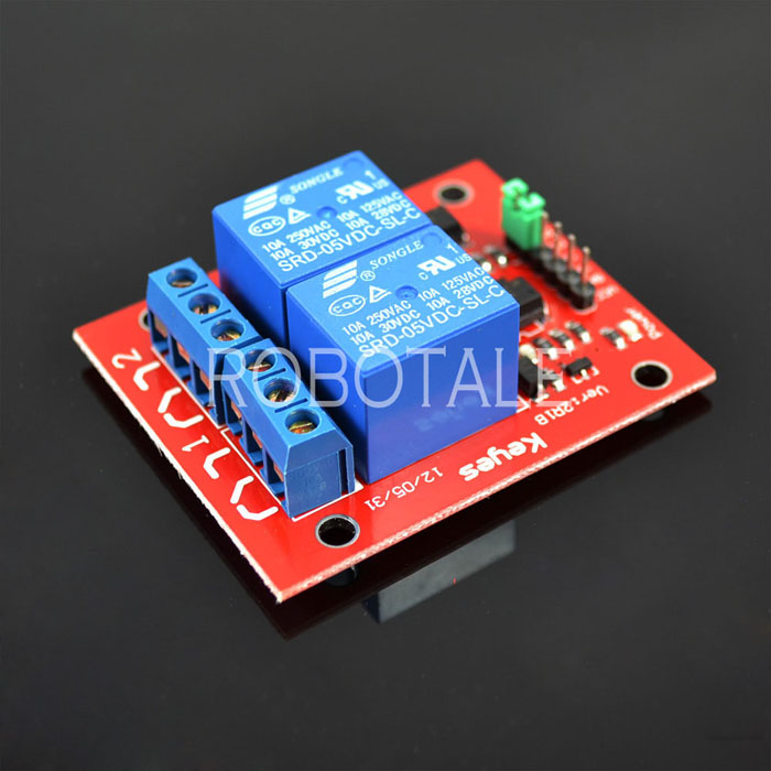
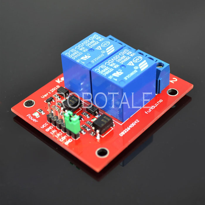
Opto-Isolated 2 Channel Relay Board
รีเลย์ 2 ตัว เพื่อใช้งานในการควบคุมอุปกรณ์ไฟฟ้า รับกระแสได้สูงถึง 10 A ใช้งานได้ทั้งไฟฟ้ากระแสตรง และ กระแสสลับ รับแรงดันระดับ 5 V ตรงจาก Arduino board มี LED แสดงสถานะการทำงานของรีเลย์ ออกแบบให้ป้องกันวงจรด้านควบคุมออกจากด้านกำลังโดยการใช้การส่งผ่านด้วยแสง (Optocoupler) ในทุกตัวรีเลย์
บทความของร้าน Arduitronics
https://www.arduitronics.com/article/applications-of-relay-with-arduino
See more details, applications on our WIKI here:
With high-current relays, AC250V 10A ; DC30V 10A NOTE: Each relay draws about .08A (80ma) so about 4 relays are the maximum you should run from the Arduino +5V supply. (Running from USB it may be less). More than 2 relays: we recommend you use a separate 5V supply for the relays.
Dimensions here: http://arduino-info.wikispaces.com/RelayDimensions
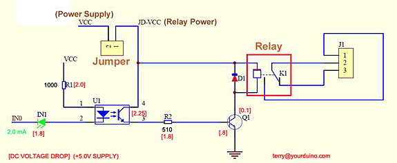
NOTES: If you want complete optical isolation, connect "Vcc" to Arduino +5 volts but do NOT connect Arduino Ground. Remove the Vcc to JD-Vcc jumper. Connect a separate +5 supply to "JD-Vcc" and board Gnd. This will supply power to the transistor drivers and relay coils.
If relay isolation is enough for your application, connect Arduino +5 and Gnd, and leave Vcc to JD-Vcc jumper in place.
NOTE: It is sometimes possible to use these relay boards with 3.3V signals, IF the JD-VCC(RelayPower) is provided from a +5V supply and the VCC to JD-VCC jumper is removed. . That 5V relay supply could be totally isolated from the 3.3V device, or have a common ground IF opto-isolation is not needed. If used with isolated 3.3V signals, VCC (To the input of the opto-isolator, next to the IN pins) should be connected to the 3.3V device's +3.3V supply. NOTE: Some RaspberryPi users have found that some relays are reliable and others do not actuate sometimes. It may be necessary to change the value of R1 from 1000 ohms to something like 220 ohms, or supply +5V to the VCC connection.
NOTE: The digital inputs from Arduino are Active LOW: The relay actuates and an LED lights whe the input pin is LOW, and turns off on HIGH. See the Wiki article for how-to assure relays do not activate at power-on time.
Schematic Diagram:
วิธีการชำระเงิน
ชำระเงินค่าสินค้าโดยการโอนเงินเข้าบัญชีธนาคาร KBANK, SCB, BBL,TMB
กรุณาเก็บหลักฐานการโอนเงินของท่านไว้เพื่อแจ้งการชำระเงินด้วยค่ะ
ท่านสามารถแจ้งการชำระเงินผ่านระบบอัตโนมัติได้โดย Click Link ข้างล่างค่ะ
https://www.arduitronics.com/informpayment
ชำระเงินผ่านธนาคาร


@rfm0967y
ติดต่อสอบถาม
Join เป็นสมาชิกร้านค้า
MEMBER
