
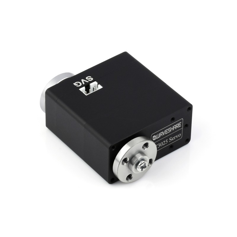
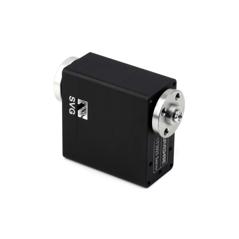
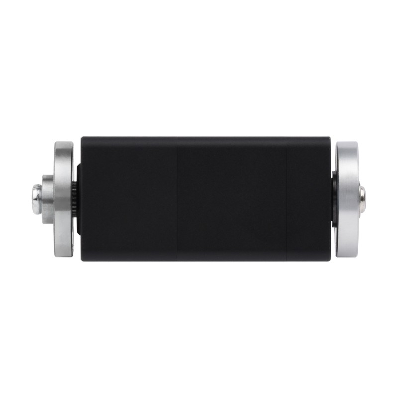
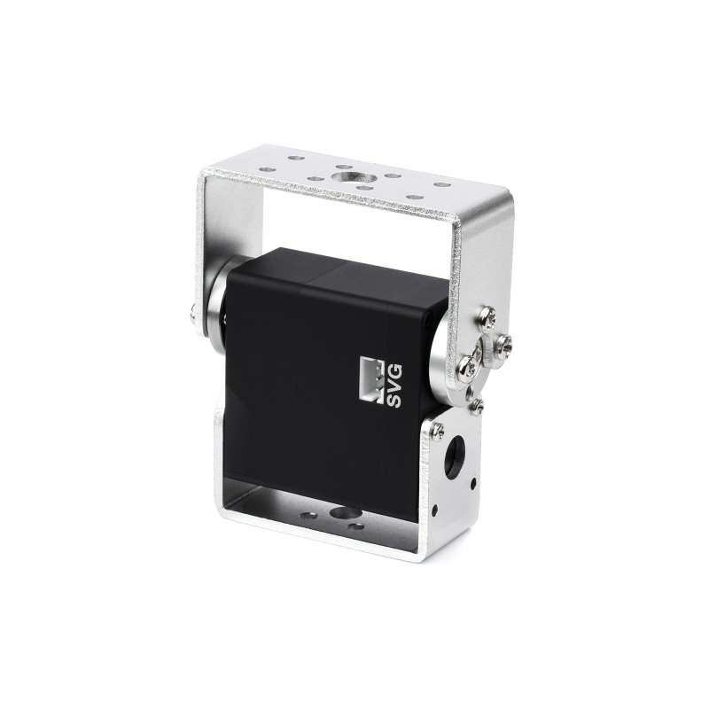
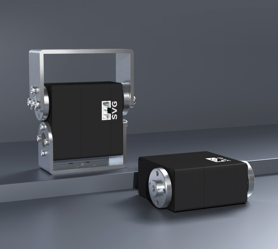
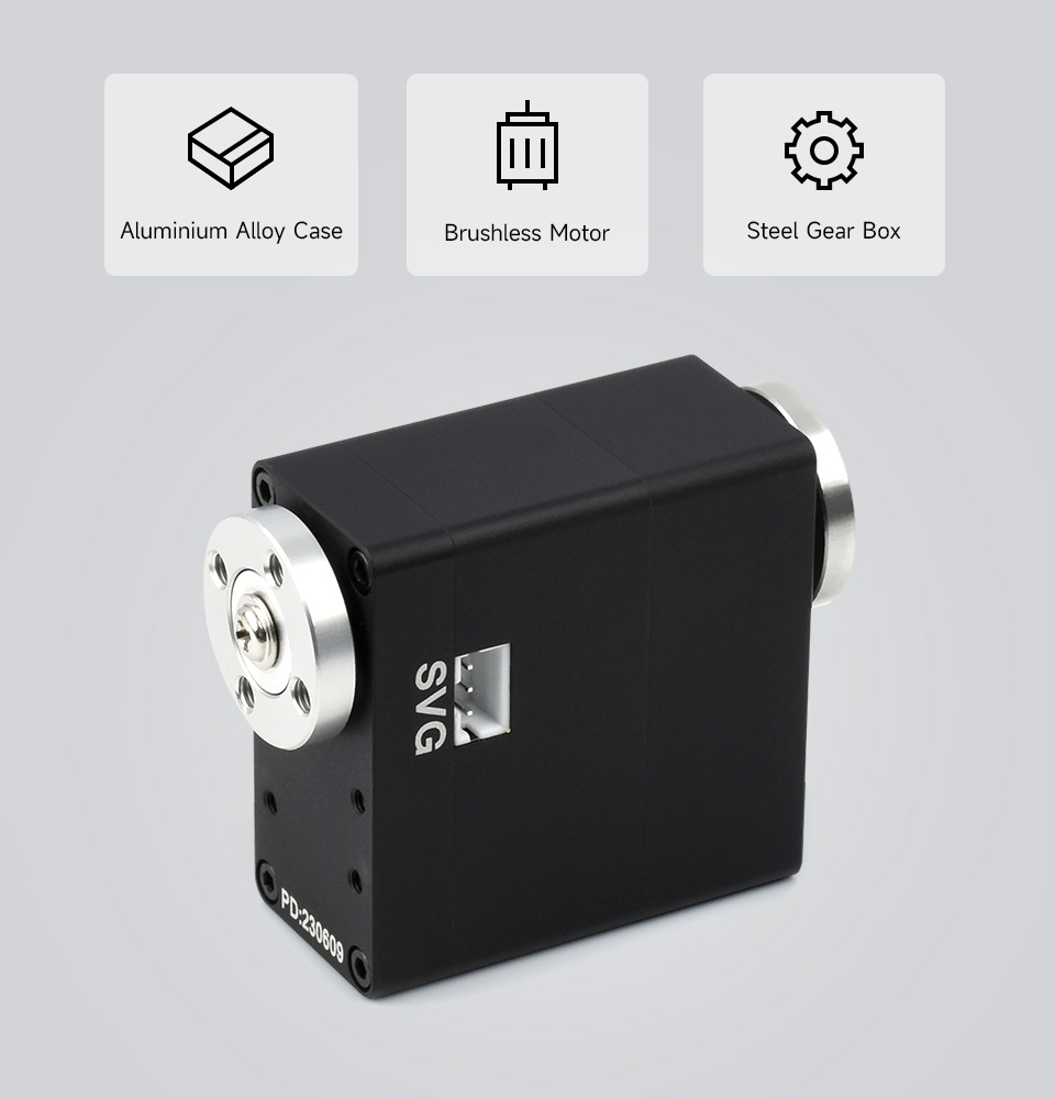
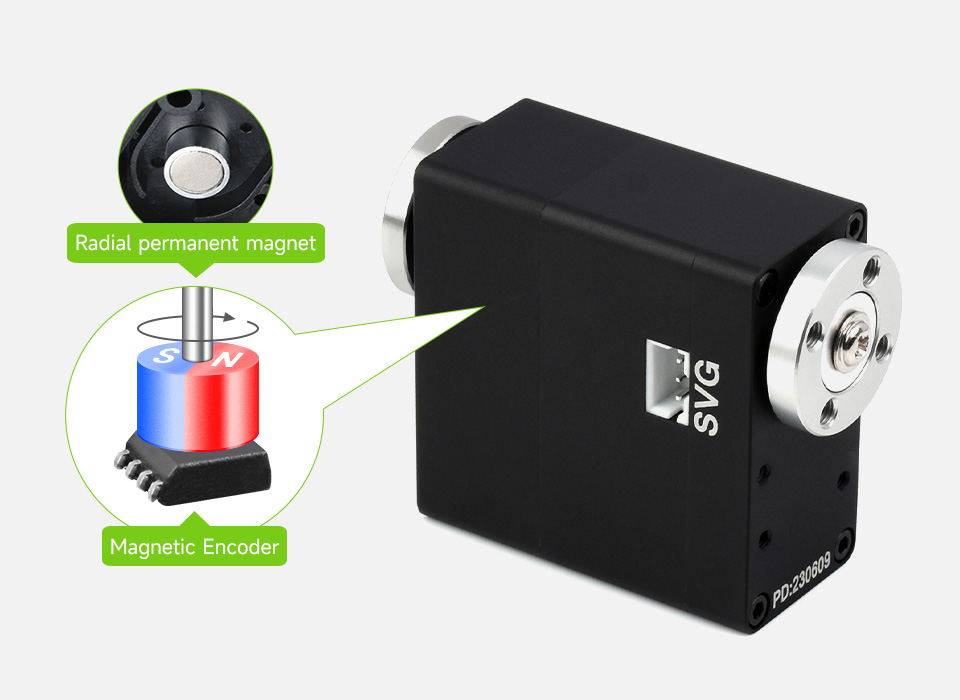
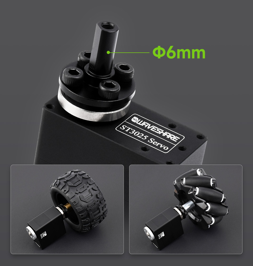
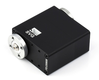
40kg.cm Metal Serial Bus Servo, High Precision And Large Torque, With Programmable 360 Degrees Magnetic Encoder and Brushless Motor (แท้จาก Waveshare)


รายละเอียดสินค้า
40kg.Cm Metal Serial Bus Servo, Wide Range Voltage, High Precision And Large Torque, With Programmable 360 Degrees Magnetic Encoder And Brushless Motor, Two-Way Feedback, Servo/Motor Mode Switchable
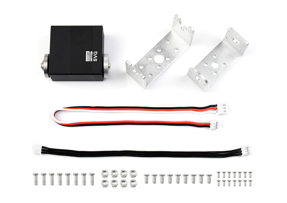
สินค้าประกอบด้วย


We provide the open-source web control demo of the servo driver board and a secondary development tutorial, which can be directly used for remote setting and remote control of the servo. At the same time, we also provide a 3D model for you to build your project quickly.
How to Use the Hardware
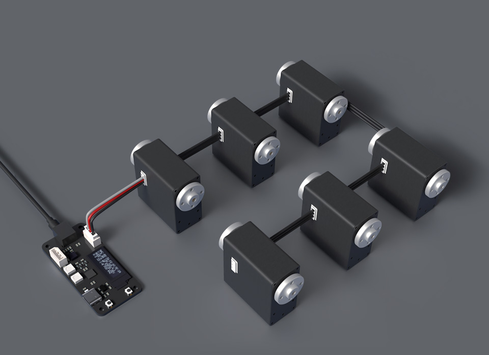
- You can use our Servo Driver to control the bus servo.
- If you want to use the bus servo in your own project, you can refer to the following schematic diagram:
Serial bus servo drive circuit schematic.
How to Use the Software
ESP32 Flash Download Tool
Generally, we control the ST series servos by compiling and uploading the demo through the Arduino IDE. However, compiling through Arduino requires installing various dependency libraries before use. Therefore, we provide an ESP32 download tool. With this tool, users can download the demo to the driver board without needing to download other dependency libraries or the Arduino IDE software.
- Click here to download ESP32 Flash Download Tool. Once downloaded, extract the files and double-click on the "flash_download_tool_3.9.5.exe" program. After opening, two windows will appear. The UI interface of the download tool is the one you need to operate, while the other window serves as a terminal to display the working status of the download tool.
- In the "DOWNLOAD TOOL MODE" interface, select Chip Type as ESP32 and WorkMode as Factory. When using Factory to call the binary file, it will use a relative path, eliminating the need for users to manually input the binary file path. After making these selections, click OK.

- In this software interface, keep the "LockSettings" option checked. On the right side, you can simultaneously upload demos to 8 driver boards. Next, connect the servo driver board to the computer using a USB cable. Click on "COM" and select the newly appeared COM port (in my case, it's COM3). BAUD is used to set the download speed, higher values result in faster speeds, with the ESP32 supporting speeds up to 921600.

- After selecting, click START to begin uploading the demo. Once the upload is complete, "IDLE" will change to "FINISH". After completing this process, you can disconnect the USB connection between the servo driver board and the computer. Then, connect the servos to the servo driver board, provide power to the driver board, and start controlling the ST series servos.


Compile Arduino IDE
- We provide ST3025 servo demos for the serial bus servo driver board, you can control ST series servos by downloading this open-source demo (Arduino) on the serial bus servo driver board, the following is the specific method:
Install Arduino IDE
- You can directly click this link to download the Arduino IDE from Arduino.cc.

- Choose the Arduino IDE suitable for your system.

- Run the installation package.

- Click on I Agree.

- Check Install USB driver and Associate.ino files, then click Next.

- Select the installation path of Arduino IDE, then click Install.

- Wait for the installation to complete.

- Install the required drivers.
- Click to install.

- Click to install.

- Click to install.

- Arduino IDE installation is complete.

Install Arduino Core for the ESP32
- Run Arduino IDE, click File.

- Click on Preferences.

- Fill https://dl.espressif.com/dl/package_esp32_index.json in Additional Boards Manager URLs and click OK.

- Restart the IDE, click Tools > Board > Boards Manager to open the Boards Manager.
- Fill in ESP32 and click Install. [Note: ESP32 version 1.0.6 needs to be installed here.]

- Wait for the installation to complete.

- After installation, you can use Arduino IDE to develop ESP32.
Download the Program & Install Dependency Libraries
- Please install the following libraries through Manage Libraries:
- Adafruit SSD1306
- Adafruit NeoPixel
- Click Tools > Manage Libraries to open the library manager.

- Enter the libraries that need to be installed through the library manager in the search box, and install:
- Adafruit SSD1306
- Adafruit NeoPixel
- Click "Update", and if there is no "Update", please click "Install" for the newest version.


- Download the bus servo library and the Arduino program for the servo driver board:
- ServoDriverST Open Source Program (Arduino)
- After downloading, unzip it and you can get the product program.
- Copy the SCServo folder to \Documents\Arduino\libraries after decompression, and install them for controlling the servo.
Upload the Program to Robot
- Double click to run SERVO DRIVER WITH ESP32 ST/ServoDriverST/ServoDriverST.ino.

- Click Tools -> Port to remember the existing COM Port, no need to click it.
- The COM displayed here is different for different computers, remember this COM.

- Connect the driver board and computer.
- Click Tools -> Port, and click on this new COM.
- The newly-appearing COM is different for different computers, click it.

- Click Tools -> Boards -> ESP32 Arduino -> ESP32 Dev Module and select ESP32 Dev Module.

- Other settings are as follows:
Upload Speed: "921600"
CPU Frequency: "240MHz(WiFi/BT)"
Flash Frequency: "80MHz"
Flash Mode: "QIO"
Flash Size: "4MB(32Mb)"
'''Partition Scheme: "Huge APP(3MB No OTA/1MB SPIFFS)"
PSRAM: "Disabled"'''
- Click "Upload" in the upper left corner to upload the demo.
- Note that the automatic downloading circuit will fail when WAVEGO uses the serial port to connect with the Raspberry Pi. You need to disconnect the serial port from the Raspberry Pi before uploading the program to WAVEGO.

- Wait for uploading the demo.
- After displaying "Leaving... Hard resetting via RTS pin...", it means that the upload has been successful.

Product Usage Tutorial
- The following tutorial uses servo driver by default to explain how to use the servo, if you need to use it in your own project, you can refer to the sample program and the bus servo drive circuit schematic for secondary development.
- The factory default ID of the servo is 1. Among the servos connected to the same servo drive board, the same ID can only correspond to one servo, and there cannot be more than one servo with the same ID in the one control circuit. When you set the ID for the servo, try to ensure that only one servo whose ID is to be changed is connected to the driver board. After the ID is changed, it will be permanently saved in the servo and will not be lost even if the power is off.
- First of all, you need to set an independent ID for each servo. When setting an ID for one servo, the driver board should not be connected to other servos.
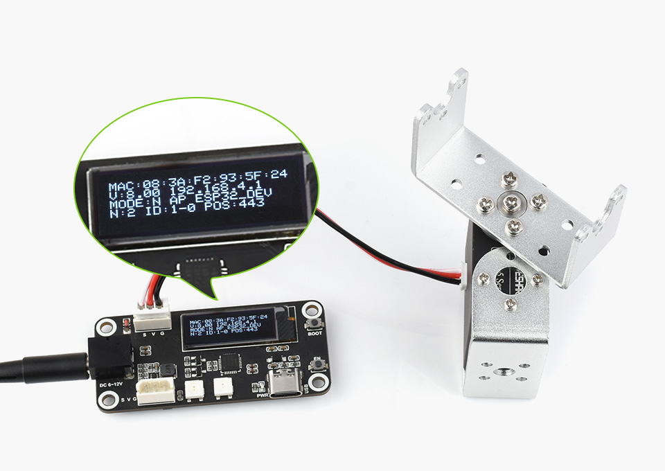
- If you use the ST3025 servo, after connecting it to the driver board, you need to provide 6-12.6V (12V is recommended) via the DC port (5.5*2.1mm) on the board, and the port will directly power the servo. If you use a large number of servos, you need to provide enough currents for the port.
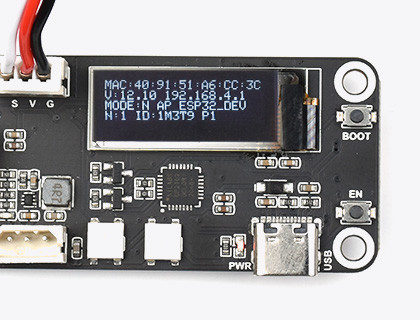
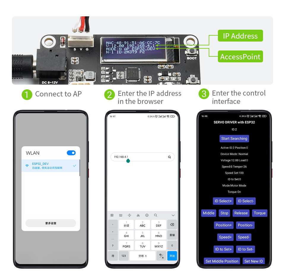
- After the driver board is powered on, a WiFi hotspot will be created by default. The default hotspot name is ESP32_DEV, and its password is 12345678. Please connect to this hotspot with your phone.
- After connecting to the hotspot issued by the servo driver board, it is recommended to use Google Chrome to access the address 192.168.4.1. Noted that the phone will fail to verify the server with ping after connecting the WiFi, so it may automatically switch to the other known WiFi. In this case, you should connect ESP32_DEV again, and the phone will not connect to other WiFi automatically after the reconnection is successful.
- The driver board will automatically scan the servo ID (0-20) when it is powered on (in order to save the boot time). If your servo ID is more than 20, you must change the MAX_ID value in ServoDriverST.ino and upload it to the driver board again.

- If the servo is connected after the driver board is powered on, you need to click Start Searchingon the mobile browser page to scan again.
- Active IDis the currently selected servo ID number, ID to Setis the new ID number to be set, adjust the value of ID to Setthrough ID to Set+andID to Set-, and press the Set New ID button to set the servo ID Active ID as ID to Set.
- When the IDs of all servos are set, you can connect them all. If you do not restart the device, you need to clickStart Searchingto scan all servos.
- ID: shows all ID numbers of servos currently connected to the servo driver board.
- Active ID The currently selected servo ID number, and the subsequent operations are all controlling thisActive ID servo.
- You can select the Active ID servo via the ID to Set+ and ID to Set- buttons.
- Middlekey, you can turn the servo to the middle position, the position range of the servo is 0-4095, and the middle position is 2047.
- Stopkey, the default program will not let the servo move all the time. If the servo cannot be stopped after the secondary development, you can press the Stop key to hault the servo movement.
- Releasekey, press it and the servo will close torque lock (Torque Off), then you can turn the servo by hand.
- Torquekey, after pressing the servo, the servo will turn on the torque lock (Torque On), at this time, the servo will maintain the specified position with force.
- Position+key, after pressing the servo, the servo will start to rotate clockwise. When the servo is in the servo mode, it will not continue to rotate after turning to the 4095 position.
- Position-key, after pressing the servo, the servo will start to rotate counterclockwise. When the servo is in the servo mode, it will not continue to rotate after turning to the 0 position.
- Speed+ and Speed- are used to set the speed of the servo. The maximum setting for ST series servos is about 3073. The speed is the number of steps per second, 50 steps/sec≈0.732RPM.
- Set Middle Positionkey, no matter what position the current servo is in, when this key is pressed, the servo will set the current position to the middle position (2047).
- Set Servo Modekey, set the servo to servo mode, 360° absolute angle control can be performed in the servo mode, the setting will be permanently saved and will not be lost even if the power is turned off.
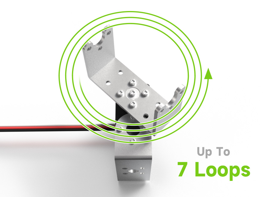
- Set Motor Modekey, set the servo to stepper motor mode, the servo can rotate continuously 30,000 steps. If you press it continuously, the motor will keep rotating. This mode can control the relative angle within ±7 circles and the number of circles will not be saved when power is off, but the stepper motor mode settings will be permanently saved even if power is off.
- Start Serial Forwardingbutton, set the servo driver board to serial forwarding mode, you can directly control the servo and get the feedback of the servo with the typeC interface on the board. This function is used to debug the servo.
- Normalkey, set the servo driver board to normal mode, in this mode, it will not send or receive any information via ESP-NOW.
- Leaderkey, set the servo driver board as the host, in this mode, the driver board continuously sends the ID, position, and speed of the current Active ID servo to the driver board of the controlled slave through the ESP-NOW protocol. After the servo driver board is turned on, the MAC:on the first line of the screen is the MAC address of this development board, which is unique, such as MAC: 08 3A F2 93 5F A8. The premise of ESP-NOW communication is to get the MAC address of the slave, please write down the address, and fill it in the broadcastAddress[] = {0x08, 0x3A, 0xF2, 0x93, 0x5F, 0xA8} of ServoDriverST.ino, then upload it to the driver of the host and the function is enabled.
- Followerkey, set the servo drive board as the slave, after changing the MAC address of the slave in the program of the host, it can act under the remote control of the host.
- RainbowONand RainbowOFFkeys are used to turn on and off the rainbow effect of RGB lights.
Secondary Development Tutorial
- Servo Initialization
Each demo that controls the servo needs to initialize the servo, and the initialization is done before it can be used.
#include <SCServo.h>
SMS_STS st;
void setup(){
Serial1.begin(1000000); //Serial port initialization, and if using devices like ESP32, custom serial ports can also be selected.
// Serial1.begin(1000000, SERIAL_8N1, RX, TX); // Custom serial ports
st.pSerial = &Serial1;
while(!Serial1) {}
}
- Change servo ID
Among the servos connected in series, each ID should only correspond to one servo. Otherwise, the servo feedback information cannot be obtained properly.
When changing the servo ID, it is advisable to ensure that the driver board is only connected to one servo. The ID will be permanently stored in the servo.
#include <SCServo.h>
SMS_STS st;
int ID_ChangeFrom = 1; // The original ID of the servo whose ID is to be changed is factory defaulted to 1.
int ID_Changeto = 2; // New ID
void setup(){
Serial1.begin(1000000);
st.pSerial = &Serial1;
while(!Serial1) {}

st.unLockEprom(ID_ChangeFrom); //Unlock EPROM-SAFE
st.writeByte(ID_ChangeFrom, SMS_STS_ID, ID_Changeto);//Change ID
st.LockEprom(ID_Changeto); // Lock EPROM-SAFE
}

void loop(){
}
- Ping
Used to test whether a particular servo is properly connected.
#include <SCServo.h>
SMS_STS st;
int TEST_ID = 3; // Servo ID to be tested
void setup()
{
Serial.begin(115200);
Serial1.begin(1000000, SERIAL_8N1, RX, TX); // Custom serial ports
st.pSerial = &Serial1;
while(!Serial1) {}
}

void loop()
{
int ID = st.Ping(TEST_ID); //If you ping the servo with that ID and receive no response, it will return -1.
if(ID!=-1){
Serial.print("Servo ID:");
Serial.println(ID, DEC);
delay(100);
}else{
Serial.println("Ping servo ID error!");
delay(2000);
}
}
- Write position
Can be used to control individual servo rotation.
#include <SCServo.h>
SMS_STS st;
void setup()
{
Serial1.begin(1000000);
st.pSerial = &Serial1;
while(!Serial1) {}
}

void loop()
{
st.WritePos(1, 1000, 1500, 50); //To control the servo with ID 1, rotate it to position 1000 at a speed of 1500, with a start-stop acceleration of 50.
delay(754);//[(P1-P0)/V]*1000+100

st.WritePos(1, 20, 1500, 50); // To control the servo with ID 1, rotate it to position 20 at a speed of 1500, with a start-stop acceleration of 50.
delay(754);//[(P1-P0)/V]*1000+100
}
- Synchronous writing
Can be used to control multiple servos at the same time (rotating to different positions and at different speeds).
#include <SCServo.h>
SMS_STS st;

// the uart used to control servos.
// GPIO 18 - S_RXD, GPIO 19 - S_TXD, as default.
#define S_RXD 18 //Customize the IO of the serial port, if you don't use the custom serial port below Serial1.begin(1000000, SERIAL_8N1, S_RXD, S_TXD); you need to change to Serial1.begin(1000000);.
#define S_TXD 19

byte ID[2];
s16 Position[2];
u16 Speed[2];
byte ACC[2];

void setup()
{
Serial1.begin(1000000, SERIAL_8N1, S_RXD, S_TXD);
st.pSerial = &Serial1;
delay(1000);
ID[0] = 1; // Save the servo ID to be controlled to ID[].
ID[1] = 2; //Save the servo ID to be controlled to ID[].
Speed[0] = 3400; // Set the servo speed, Speed[0] corresponds to the servo with ID[0] above.
Speed[1] = 3400; // Set the servo speed, Speed[1] corresponds to the servo with ID[1] above.
ACC[0] = 50; // Set the start/stop acceleration, the lower the value the lower the acceleration, and the maximum can be set to 150.
ACC[1] = 50;
}

void loop()
{
Position[0] = 3000; // Set the target position of the servo with ID[0] (in this case ID 1) in the range 0-4095
Position[1] = 3000; // Set the target position of the servo with ID[1] (here with ID 2) in the range 0-4095
st.SyncWritePosEx(ID, 2, Position, Speed, ACC);//servo(ID1/ID2) speed=3400,acc=50,move to position=3000.
delay(2000);

Position[0] = 100;
Position[1] = 100;
st.SyncWritePosEx(ID, 2, Position, Speed, ACC);//servo(ID1/ID2) speed=3400,acc=50,move to position=100.
delay(2000);
}
- Get servo feedback
#define S_RXD 18
#define S_TXD 19
#include <SCServo.h>

SMS_STS sms_sts;

void setup()
{
Serial1.begin(1000000, SERIAL_8N1, S_RXD, S_TXD);
Serial.begin(115200);
sms_sts.pSerial = &Serial1;
delay(1000);
}

void loop()
{
int Pos;
int Speed;
int Load;
int Voltage;
int Temper;
int Move;
int Current;
if(sms_sts.FeedBack(1)!=-1){
Pos = sms_sts.ReadPos(-1);
Speed = sms_sts.ReadSpeed(-1);
Load = sms_sts.ReadLoad(-1);
Voltage = sms_sts.ReadVoltage(-1);
Temper = sms_sts.ReadTemper(-1);
Move = sms_sts.ReadMove(-1);
Current = sms_sts.ReadCurrent(-1);
Serial.print("Position:");
Serial.println(Pos);
Serial.print("Speed:");
Serial.println(Speed);
Serial.print("Load:");
Serial.println(Load);
Serial.print("Voltage:");
Serial.println(Voltage);
Serial.print("Temper:");
Serial.println(Temper);
Serial.print("Move:");
Serial.println(Move);
Serial.print("Current:");
Serial.println(Current);
delay(10);
}else{
Serial.println("FeedBack err");
delay(500);
}

Pos = sms_sts.ReadPos(1); // Get position feedback
if(Pos!=-1){
Serial.print("Servo position:");
Serial.println(Pos, DEC);
delay(10);
}else{
Serial.println("read position err");
delay(500);
}

Voltage = sms_sts.ReadVoltage(1); //Get voltage feedback
if(Voltage!=-1){
Serial.print("Servo Voltage:");
Serial.println(Voltage, DEC);
delay(10);
}else{
Serial.println("read Voltage err");
delay(500);
}

Temper = sms_sts.ReadTemper(1); // Get temperature feedback
if(Temper!=-1){
Serial.print("Servo temperature:");
Serial.println(Temper, DEC);
delay(10);
}else{
Serial.println("read temperature err");
delay(500);
}

Speed = sms_sts.ReadSpeed(1); // Get speed feedback
if(Speed!=-1){
Serial.print("Servo Speed:");
Serial.println(Speed, DEC);
delay(10);
}else{
Serial.println("read Speed err");
delay(500);
}

Load = sms_sts.ReadLoad(1); // Get load feedback
if(Load!=-1){
Serial.print("Servo Load:");
Serial.println(Load, DEC);
delay(10);
}else{
Serial.println("read Load err");
delay(500);
}

Current = sms_sts.ReadCurrent(1); // Get current feedback
if(Current!=-1){
Serial.print("Servo Current:");
Serial.println(Current, DEC);
delay(10);
}else{
Serial.println("read Current err");
delay(500);
}

Move = sms_sts.ReadMove(1); // Getting movement feedback
if(Move!=-1){
Serial.print("Servo Move:");
Serial.println(Move, DEC);
delay(10);
}else{
Serial.println("read Move err");
delay(500);
}
Serial.println();
}
Resource
3D Model

- Open-source robotic arm model based on ST3025 Servo.
- Open-source robotic arm model F3Z
- Open-source robotic arm model STEP

- Open-source quadruped robot model based on ST3025 Servo.
- Open-source quadruped robot model F3Z
- Open-source quadruped robot model STEP

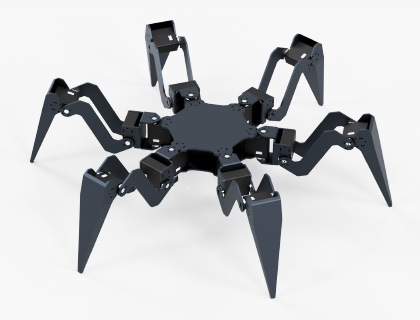
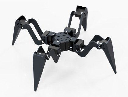
- Open-source hexapod robot model based on ST3025 Servo.
- Open-source hexapod robot model F3Z
- Open-source hexapod robot model STEP

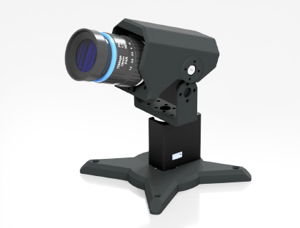
- Open-source camera gimbal model based on ST3025 Servo.
- Open-source gimbal model F3Z
- Open-source gimbal model STEP
- Servo driver board STEP model
- ST302 Servo STEP Model
Document
- Serial Bus Servo Driver User Manual
- Serial Bus Servo Driver Circuit Schematic
- Communication Protocol User Manual
Demo
Software
วิธีการชำระเงิน
ชำระเงินค่าสินค้าโดยการโอนเงินเข้าบัญชีธนาคาร KBANK, SCB, BBL,TMB
กรุณาเก็บหลักฐานการโอนเงินของท่านไว้เพื่อแจ้งการชำระเงินด้วยค่ะ
ท่านสามารถแจ้งการชำระเงินผ่านระบบอัตโนมัติได้โดย Click Link ข้างล่างค่ะ
https://www.arduitronics.com/informpayment
ชำระเงินผ่านธนาคาร


@rfm0967y
ติดต่อสอบถาม
Join เป็นสมาชิกร้านค้า
MEMBER
