
Beetle ESP32 C6 Mini Development Board for Wireless Smart Wearable Device (Supports BLE / Matter) - แท้จาก DFRobot

| รหัสสินค้า | BA00296 |
| หมวดหมู่ | WiFi ESP32-C6 |
| ราคา | 395.00 บาท |
| สถานะสินค้า | พร้อมส่ง |
| จำนวน | ชิ้น |

รายละเอียดสินค้า

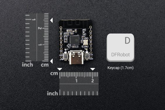
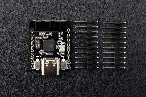
Figure 1: Comparison of the size between the Beetle ESP32-C6 and the keycap
Multiple transmission protocol support to expand wireless connectivity
Boasting support for multiple communication protocols, the Beetle ESP32-C6 expands wireless connectivity options. By supporting Wi-Fi and Thread protocols, it enables the creation of Matter Wi-Fi terminal devices and Matter Thread terminal devices, facilitating seamless communication and collaboration among multiple systems and platforms in smart home setups. Additionally, the Beetle ESP32-C6 supports BLE (Bluetooth Low Energy) and Zigbee communication protocols, making it suitable for use as a Thread border router, Matter gateway, or Zigbee bridge when combined with other MCUs.
.jpg "Beetle ESP32-C6 supports BLE, Zigbee, Wi-Fi 6 and Thread")
Figure 2: Beetle ESP32-C6 supports BLE, Zigbee, Wi-Fi 6 and Thread
Support Wi-Fi 6 to realize ultra-low power consumption IoT devices
With Wi-Fi 6 support, the Beetle ESP32-C6 enables the realization of ultra-low-power IoT devices. As the first Espressif chip to support the Wi-Fi 6 (802.11ax) protocol, it offers improved network capacity, allowing devices to operate efficiently with low latency. Moreover, Wi-Fi 6's Target Wake Time (TWT) technology effectively reduces device power consumption, extending battery life and ensuring long-lasting device performance.
 technology")
Figure 3: Wi-Fi 6's Target Wake Time (TWT) technology
FEATURES
- Ultra-compact size, measuring only 25*20.5mm.
- Equipped with the ESP32-C6 chip, it supports communication protocols including Wi-Fi, BLE, Zigbee, and Thread.
- Supports Wi-Fi 6 protocol for lower latency and lower power consumption.
- Ultra-low power consumption with deep sleep at 14uA.
- Integrated lithium battery charging functionality.
- Supports battery voltage detection, providing insights into device power levels.
APPLICATIONS
- Electronic Badge
- Backpack Charm
- Pet Tracker
- Electronic Watch
- Smart Button
- Smart Lighting
- Human-Interactive Device

SPECIFICATION
Basic Parameters
- Operating Voltage: 3.3V
- Type-C Input Voltage: 5V DC
- VIN Input Voltage: 5V DC
- Max Charging Current: 0.5A
- Sleep current: 14uA (in deep sleep mode, powered by battery)
- Operating Temperature: -10~60℃
- Dimension: 25x20.5mm/0.98x0.81”
Hardware Information
- Processor: RISC-V single-core processor
- Main Frequency: 160 MHz
- SRAM: 512KB
- ROM: 320KB
- Flash: 4MB
- RTC SRAM: 16KB
- USB: USB 2.0 CDC
WIFI
- WIFI Protocol: IEEE 802.11b/g/n
IEEE 802.11ax (20 MHz-only non-AP mode) - Bandwidth: Support 20 MHz and 40 MHz at 2.4 GHz band
- WIFI Mode: Station, SoftAP, SoftAP+Station combined mode
- WIFI Frequency: 2.4GHz
- Frame Aggregation: TX/RX A-MPDU, TX/RX A-MSDU
Bluetooth
- Bluetooth Protocol: Bluetooth 5, Bluetooth mesh
- Bluetooth Frequency: 125 Kbps, 500 Kbps, 1 Mbps, 2 Mbps
IEEE 802.15.4
- Compatible with IEEE 802.15.4-2015 protocol
- Frequency band: 2.4GHz
- Data rate: 250Kbps
- Supports Thread 1.3 and Zigbee 3.0
Ports
- Digital I/O x13
- LED PWM 6 Channel
- SPI x1
- UART x3 (LP UART x1)
- I2C x2 (LP I2C x1)
- I2S x1
- IR Transceiver: transmit channel x5, receive channel x5
- 1 × 12-bit SAR ADC, 7 Channel
- DMA Controller: transmit channel x3, receive channel x3
DOCUMENTS
SHIPPING LIST
- Beetle ESP32 C6 Mini Development Board x1
- 10pin-2.54mm Pin Header x2
PROJECTS

Introduction:In this guide, we will use the ESP32-C6 to create a smart light bulb and integrate it into a Matter network.
Note:The FireBeetle 2 ESP32 C6 IoT Development Board used in this project can be completely replaced with the Beetle ESP32-C6.

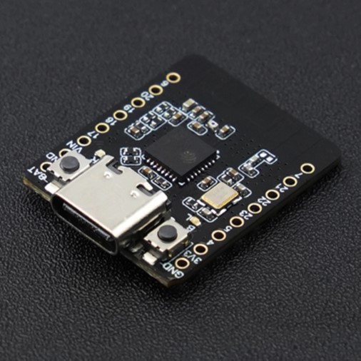
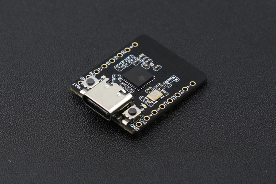
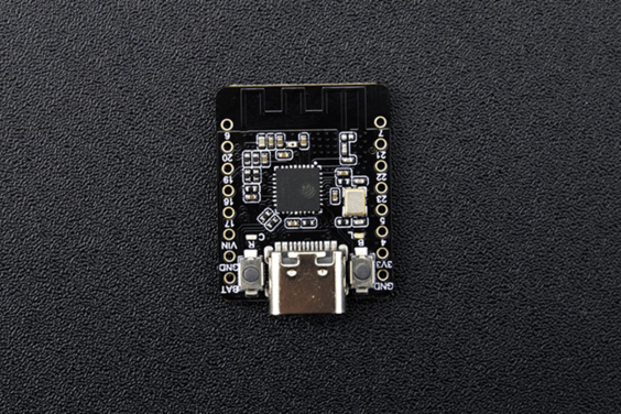
Board Overview

- Type-C:Type-C USB port
- IO15/D13:onboard LED pin
- Charge:Charging indicator
- Off: n ot plugged in power supply or fully charged
- On: charging
- Blinking: battery not connected
- RST: Reset button
- IO9/D9/BOOT: GPIO9 / Boot button
- ESP32-C6: ESP32-C6FH4 chip
- TP4057: TP4057 lithium battery charge management chip
- RT9080: 3.3V Low power LDO
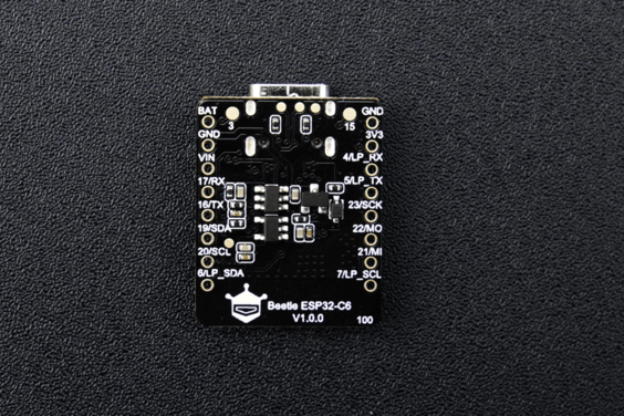
Pin Diagram

Pin Definition
- Power: Power pin
- VIN: 5V DC
- 3V3: 3.3V stable output
- GND: common ground pin
- GPIO: ESP32 default GPIO number
- Arduino: Beetle ESP32-C6 GPIO mapping in Arduino
- ADC: ESP32 default analog-to-digital conversion pin
- I2C: I2C interface
- Beetle ESP32-C6 I2C mapping in Arduino
- LP_SDA/SCL: Low power I2C pin
- UART: UART interface
- LP_TX/RX: Low power UART pin
- SPI: Beetle ESP32-C6 SPI mapping in Arduino
- SDIO: ESP32 default SDIO pin
- JTAG: debug interface
Tutorial - First Time Use
Arduino IDE Configuration
Please pay attention to the followings when using FireBeetle 2 ESP32-C6 for the first time.
- Add the json link in the IDE
- Download the core of the MCU
- Select the development board and serial port
- Open the sample code and burn it into the board
- Get to know the serial monitor
Arduino IDE compiler environment config
- Configure URL to the Arduino IDE
- Open Arduino IDE and click File->Preferences, as shown below.

- In the newly opened interface, click the button in the red circle as shown below

- Copy the following link into the new pop-up dialog box:
Stable version:https://espressif.github.io/arduino-esp32/package_esp32_index.json
Development release:https://espressif.github.io/arduino-esp32/package_esp32_dev_index.json
Note:
-
Please choose the appropriate version according to Chip Support Situation.
-
If you have installed another environment before, you can press Enter key at the beginning or end of the previous link and paste the link at a new line.

- Click OK. Update the board. Open Tools->Board:->Boards Manager... as shown below:

- Boards Manager will automatically update the boards as shown below:

- After completing the update, you can enter esp32 at the top, select esp32 and click install when the following occurs (It's recommended to install the latest version):

- Wait for the end of the following progress bar:

- After completing the installation, the list will show that the esp32 has been installed, as shown below:

- Click Tools->Board, select DFRobot FireBeetle 2 ESP32-C6.

- Before starting, you need to configure the following settings (when you select Disabled, the serial port is RX(17), TX(16), if you need to print on the Arduino monitor via USB, you need to select Enable)

- Click Port to select the corresponding serial port.
LED Blinking
The default pin for the onboard LED is pin 15.
Sample Code
- Copy the codes above to the code editing box.
- Click the arrow to complile the program and burn it into your development board.
Burning Successful

mage above shows that your codes have been successfully loaded into the board. Then, the onboard LED will start blinking.
Basic Tutorial
The basic tutorial includes the use of Battery voltage detection, PWM, interrupt, serial port, servo, and SD card.
Advanced Tutorial
The advanced tutorial domenstrates how to use screen, Bluetooth, WiFi, ESP-NOW, one-key for networking config and sample projects.
FAQ
1. What will cause burning error?
- There is no delay or too short delay in Loop.

- The USB cannot be recognized by the PC as some functions are incorrectlly called.
How to solve
- Press and hold BOOT, click RST, and then release the BOOT button to burn.
Principle During the initialization process, ESP32 undertakes a verification of the voltage level on the BOOT (IO9) pin. If the voltage level is determined to be high, the system proceeds with a normal startup. In contrast, if the voltage level is deemed to be low, the device enters into the programming mode. By default, the BOOT pin maintains a high voltage level, but it transitions to a low level when a button is pressed.
2. Data cannot be printed on serial port
- Check if the USB CDC is enabled
- Check print information using other serial debugger.
วิธีการชำระเงิน
ชำระเงินค่าสินค้าโดยการโอนเงินเข้าบัญชีธนาคาร KBANK, SCB, BBL,TMB
กรุณาเก็บหลักฐานการโอนเงินของท่านไว้เพื่อแจ้งการชำระเงินด้วยค่ะ
ท่านสามารถแจ้งการชำระเงินผ่านระบบอัตโนมัติได้โดย Click Link ข้างล่างค่ะ
https://www.arduitronics.com/informpayment
ชำระเงินผ่านธนาคาร


@rfm0967y
ติดต่อสอบถาม
Join เป็นสมาชิกร้านค้า
MEMBER
