
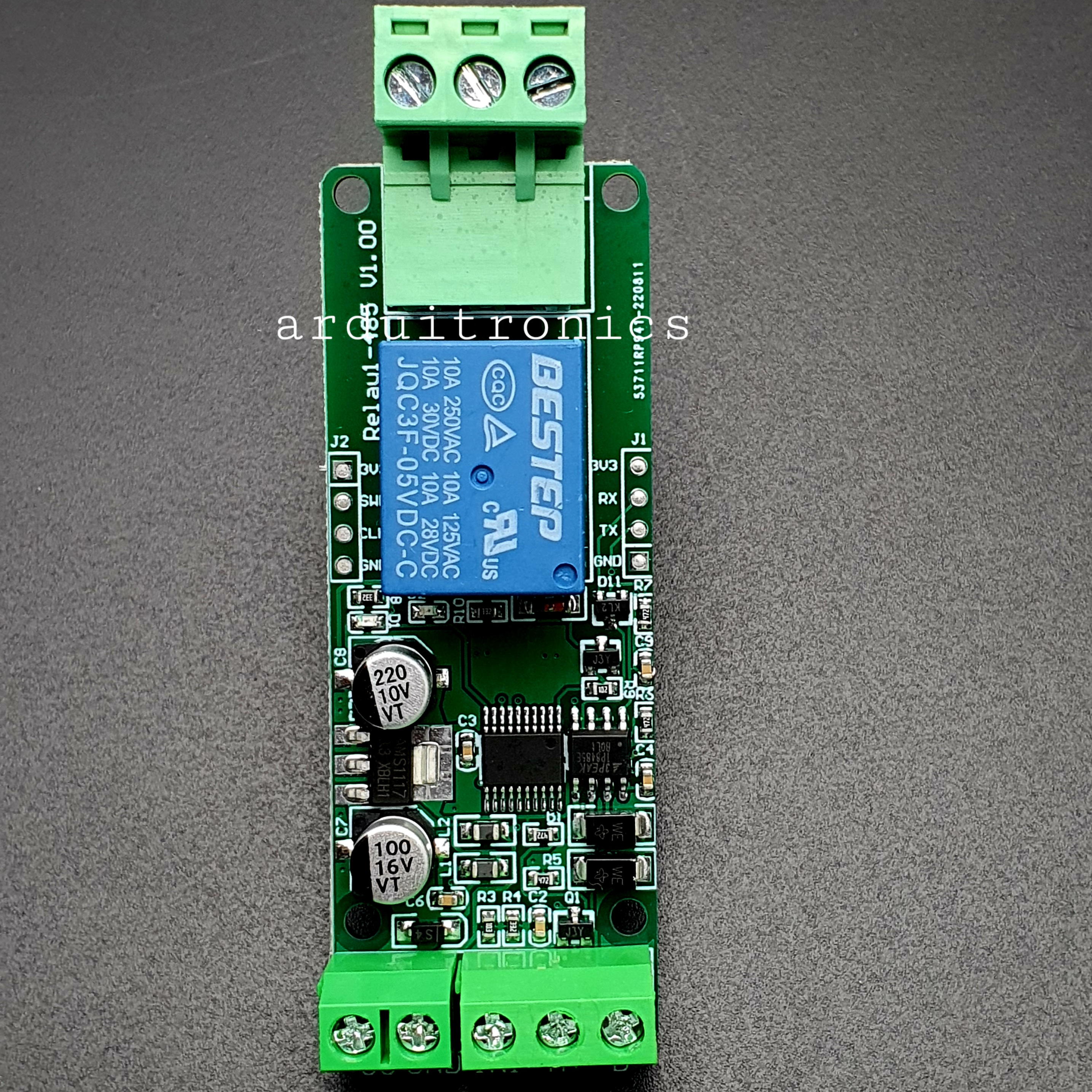
Modbus - RTU 1 Channel Relay Module RS485/TTL (5V)
| รหัสสินค้า | AG00794 |
| หมวดหมู่ | 1 Channel Relay |
| ราคา | 145.00 บาท |
| สถานะสินค้า | พร้อมส่ง |
| จำนวน | ชิ้น |

รายละเอียดสินค้า
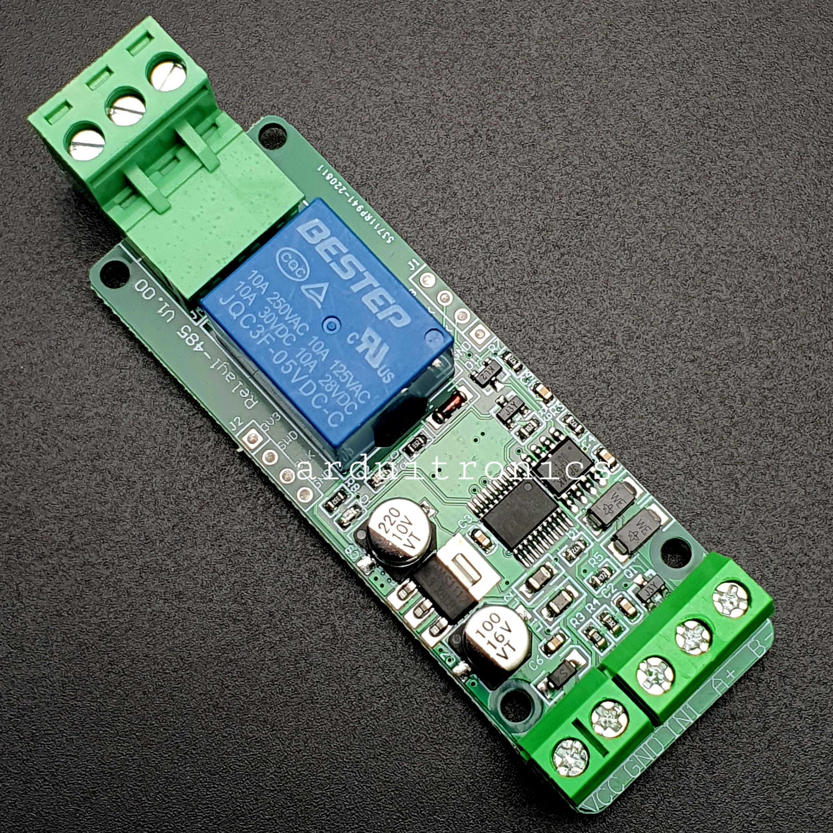
บอร์ดรีเลย์ Modbus RTU/RS485 1 ช่อง 5V ใช้ควบคุมอุปกรณ์ผ่าน Modbus RTU หรือ RS485 ใช้แรงดันไฟฟ้า 5V ในการทำงาน
This is a one channel Modbus RTU relay module equipped with stable 8-bit MCU and RS485 level communication chip, adopting standard MODBUS RTU format RS485 communication protocol. It can realize 2-bit input signal detection and provides a 2-bit relay output. It can be used for digital detection or power control occasions.
Specification:
- Model: GY18123
- Work Voltage: 7 ~ 24VDC
- Baud Rate: 4800/9600/19600bps (default 9600bps)
- Optocoupler Input Signal: 3.3 ~ 30VDC
- Set Address: 1 ~ 255
- Relay Contorl Mode: ON/OFF, Delay_ON, Delay_OFF mode
- Delay Time: 0 ~ 6553.5s
- Load: AC 250V 10A / DC 28V 10A
- Protocol: Modbus RTU
- Interface: RS485/TTL UART
- Control Channel: 1 channel
- Operating Temperature: -20 ~ +85°C
- Operating Humidity: 5% ~ 95%RH
- Module Size: 85 x 49 x 19mm
- Weight: 24g
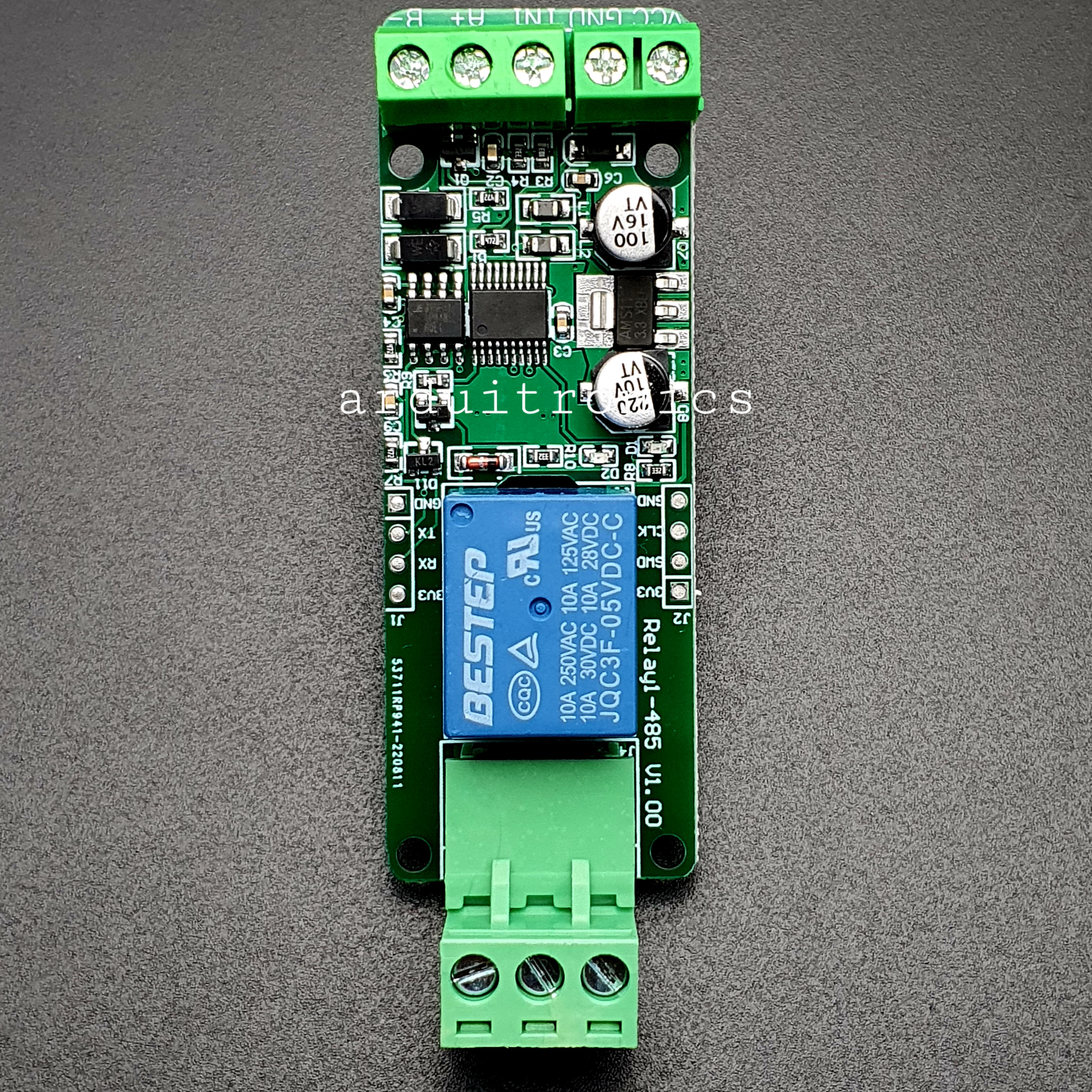
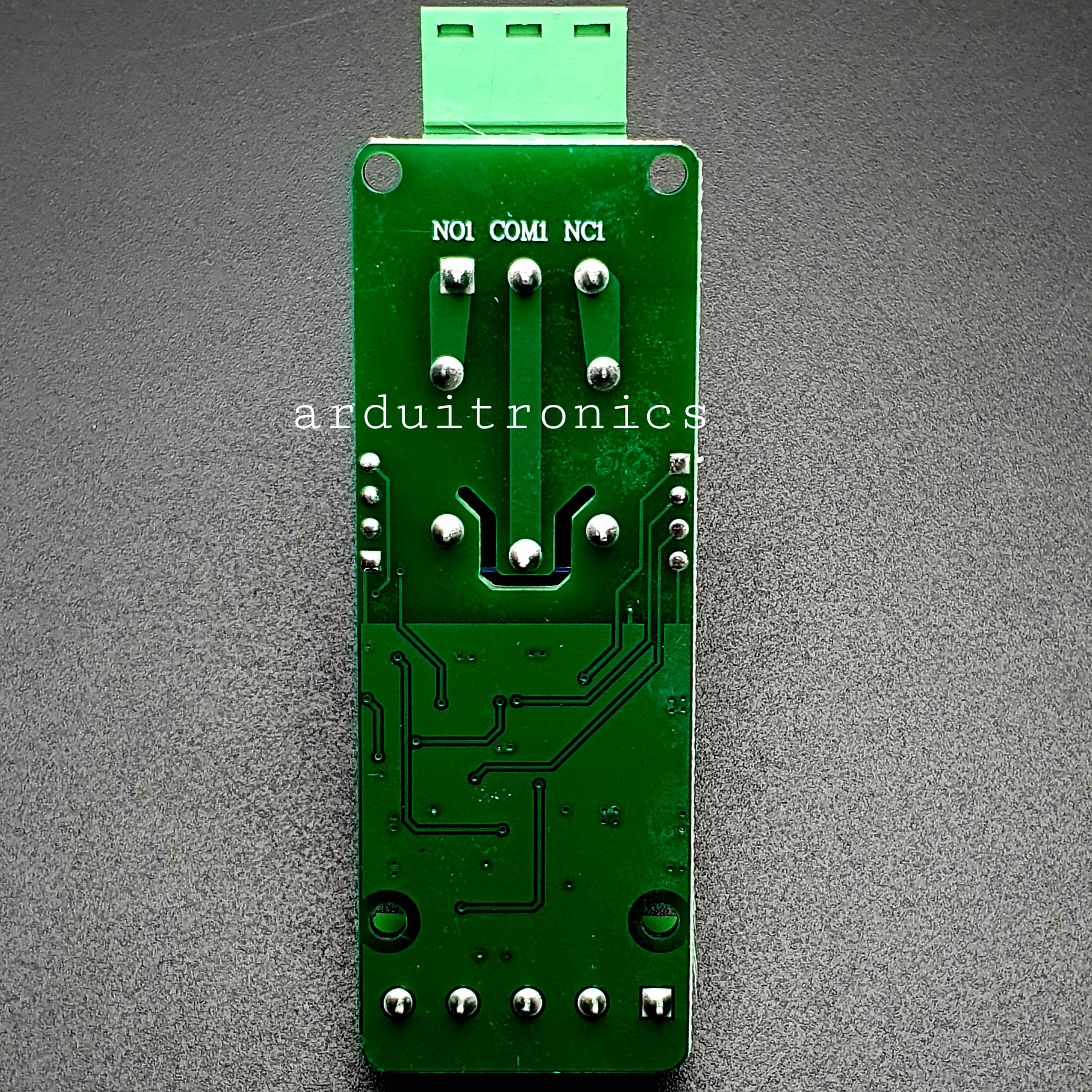
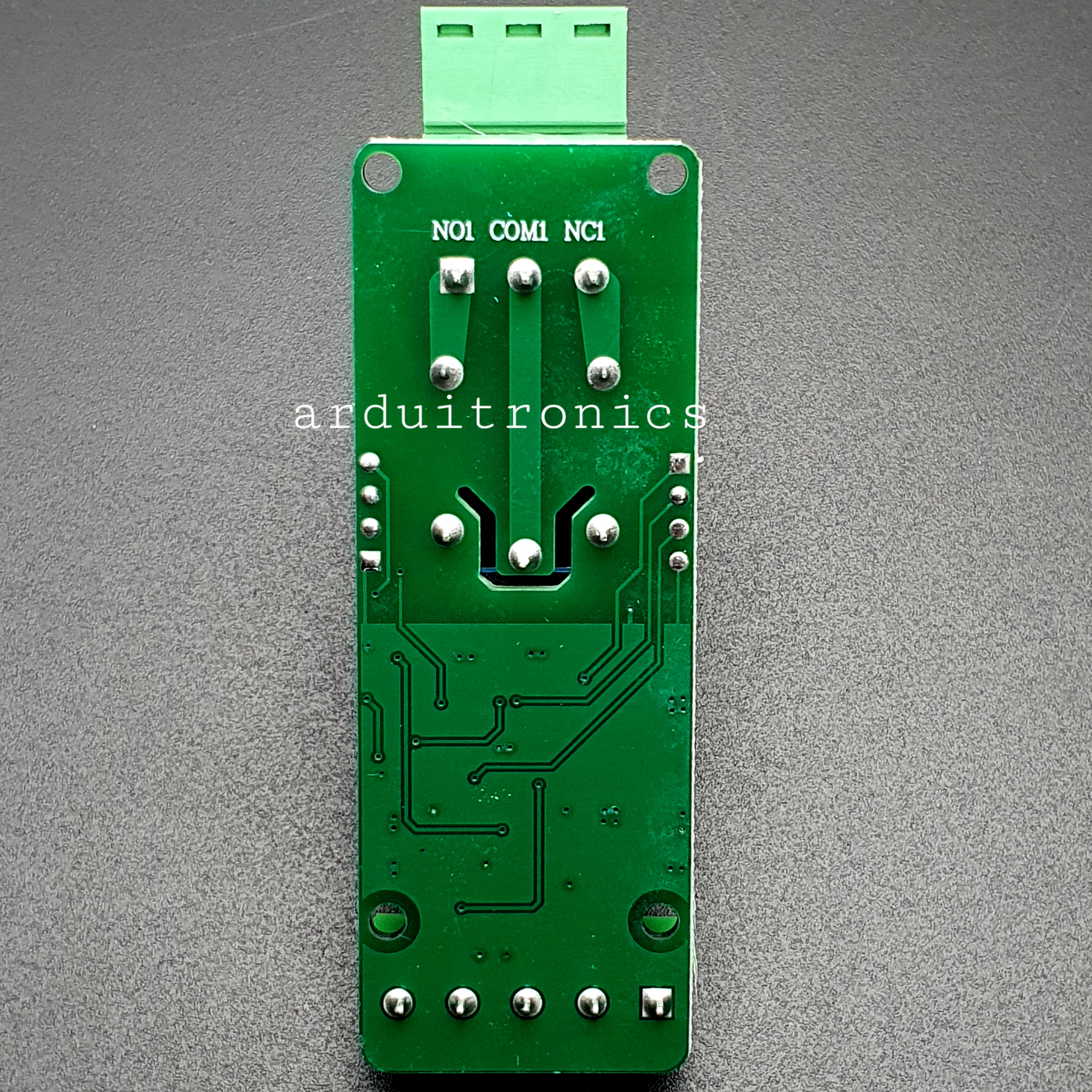
Wiring Diagram

Modbus RTU Command
Suppose the device address is 0xFF so return 00 10 00 00 00 01 02 00 FF EB 80 and the 9th btye is the devices address.
Turn ON CH_1 Relay(Normal Mode)
- Send: FF 05 00 00 FF 00 99 E4
- Return: FF 05 00 00 FF 00 99 E4
- The 3rd and 4th byte are relay addresses. So it can be 0x0000,0x0001,0x0002,0x0003
- The 5th and 6th byte are relay data .0xFF00 means turn ON relay and 0x0000 means turn OFF relay
Turn OFF CH_1 Relay(Normal Mode)
- Send: FF 05 00 00 00 00 D8 14
- Return: FF 05 00 00 00 00 D8 14
Turn ON All relays
- Send: FF 0F 00 00 00 08 01 FF 30 1D
- Return: FF 0F 00 00 00 08 41 D3
Turn OFF All relays
- Send: FF 0F 00 00 00 08 01 00 70 5D
- Return: FF 0F 00 00 00 08 41 D3
Set device address to 0x01
- Send: 00 10 00 00 00 01 02 00 01 6A 00
- Return: 00 10 00 00 00 01 02 00 01 6A 00
- Note: The 9th btye is the device address
Set device address to 0xFF
- Send: 00 10 00 00 00 01 02 00 FF EB 80
- Return: 00 10 00 00 00 01 02 00 FF EB 80
Read device address
- Send: 00 03 00 00 00 01 85 DB
- Return: 00 03 02 00 FF C5 C4
- Note: The 5th btye is the device address
Read relay status
- Send: FF 01 00 00 00 08 28 12
- Return: FF 01 01 01 A1 A0
- Note: The 4th means which one relay.0 means OFF and 1 means ON
Read optocoupler input staturs
- Send: FF 02 00 00 00 08 6C 12
- Return: FF 02 01 01 51 A0
- Note: The 4th means which one input.0 means low level signal input and 1 means high level signal input
Set baud rate 4800bps
- Send: FF 10 03 E9 00 01 02 00 02 4A 0C
- Return: FF 10 03 E9 00 01 C5 A7
- Note: The 9th btye is baud rate value.0x02 is 4800bps.0x03 is 9600bps.0x04 is 19200bps
Set baud rate 9600bps
- Send: FF 10 03 E9 00 01 02 00 03 8B CC
- Return: FF 10 03 E9 00 01 C5 A7
Set baud rate 19200bps
- Send: FF 10 03 E9 00 01 02 00 04 CA 0E
- Return: FF 10 03 E9 00 01 C5 A7
Turn ON CH_1 Relay(2S Flashing Mode)
- Send: FF 10 00 03 00 02 04 00 04 00 14 C5 9F
- Return: FF 10 00 03 00 02 A4 16
- Note: The 3rd and 4th byte are relay addresses.So CH1~CH4 can be 0x0003,0x0008,0x000D,0x0012
The 10th and 11th byte are delay time in second.The minimum delay time is 0.1s.Relay will OFF after delay time.So the delay time in this command is : 0x0014*0.1=2S
Turn OFF CH_1 Relay(3S Flashing Mode)
- Send: FF 10 00 03 00 02 04 00 02 00 1E A5 99
- Return: FF 10 00 03 00 02 A4 16
- Note: Relay will ON after delay time.So the delay time in this command is : 0x001E*0.1=3S
Library :
วิธีการชำระเงิน
ชำระเงินค่าสินค้าโดยการโอนเงินเข้าบัญชีธนาคาร KBANK, SCB, BBL,TMB
กรุณาเก็บหลักฐานการโอนเงินของท่านไว้เพื่อแจ้งการชำระเงินด้วยค่ะ
ท่านสามารถแจ้งการชำระเงินผ่านระบบอัตโนมัติได้โดย Click Link ข้างล่างค่ะ
https://www.arduitronics.com/informpayment
ชำระเงินผ่านธนาคาร


@rfm0967y
ติดต่อสอบถาม
Join เป็นสมาชิกร้านค้า
MEMBER
