
FireBeetle 2 Board ESP32-S3-U (N16R8) AIoT Microcontroller with Camera (Wi-Fi & Bluetooth on Board) - แท้จาก DFRobot

รายละเอียดสินค้า
Desription:
 Image recognition

Video picture transmission
Comparison Table
| FireBeetle 2 Board ESP32-S3 (N16R8) AIoT Microcontroller | FireBeetle 2 Board ESP32-S3-U (N16R8) AIoT Microcontroller | |
| WiFi | Soldered on the board | Routed through a cable |
| Bluetooth | Soldered on the board | Routed through a cable |
| Features | Cohesive design,more visually appealing | Better signal quality |
Features:
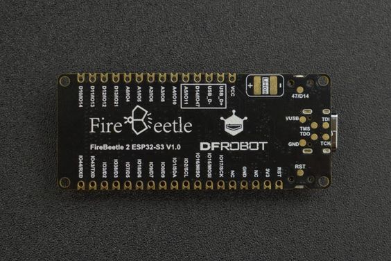
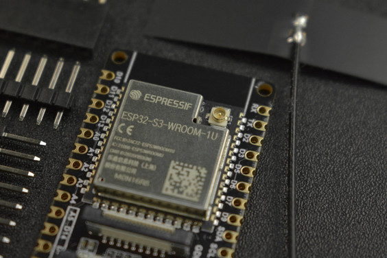
- ESP32-S3 module with AI Acceleration
- 16MB Flash & 8MB PSRAM, more storage space
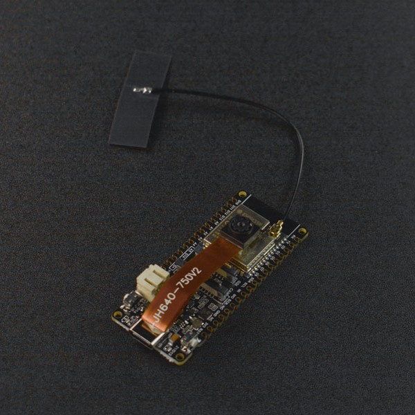
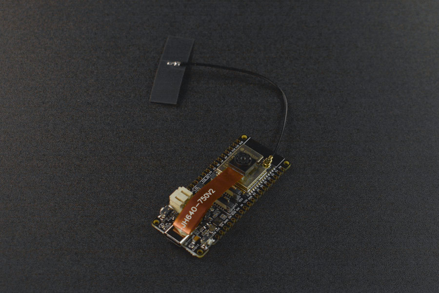
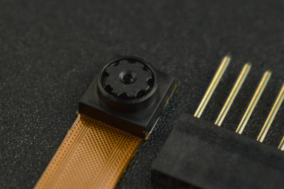
- Onboard camera interface & independent camera power supply, easy to connect and strong anti-interference
- Power management integrated, support Li-ion battery charging and hardware On/OFF controlling
- Onboard GDI for easy connection with screens
- Wi-Fi and Bluetooth 5 dual-mode communication
SPECIFICATION
Basic Parameters- Operating Voltage: 3.3V
- Type-C Input Voltage: 5V DC
- VCC Input Voltage: 5V DC
- Max Charging Current: 1A
- Operating Temperature: -20 to 70℃
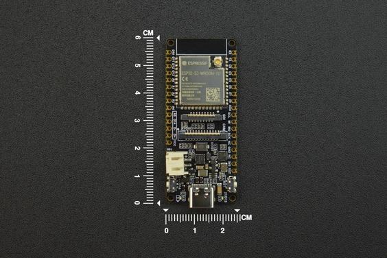
- Dimension: 25.4x60mm/1x2.36"
WIFI
Bluetooth
Ports
PROJECTS
Project: DIY a plant growth recorder with ESP32 S3
Introduction: I plan to create a DIY plant growth recorder that will allow me to monitor the entire growth process of my plants from seedling to maturity, while tracking environmental conditions throughout.
 ESP32 S3 Project - DIY a plant growth recorder with ESP32 S3
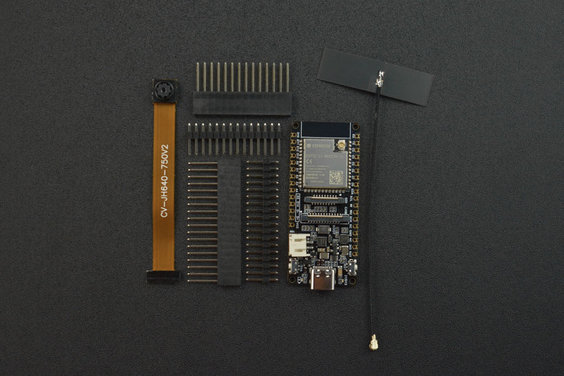
SHIPPING LIST
- FireBeetle 2 Board ESP32-S3 (N16R8) AIoT Microcontroller (Supports Wi-Fi & Bluetooth) x1
- OV2640 Camera x1
- 2.4GHz WIFI&BLE Antenna x1
- 18pin-2.54mm Pin Header x1
- 18pin-2.54mm Female Header x1
- 14pin-2.54mm Pin Header x1
- 14pin-2.54mm Female Header x1
Tutorial - First Time Use
Arduino IDE Configuration
Please pay attention to the followings when using FireBeetle 2 ESP32-S3 for the first time.
- Add the json link in the IDE
- Download the core of the MCU
- Select the development board and serial port
- Open the sample code and burn it into the board
- Get to know the serial monitor
Arduino IDE compiler environment config
- Configure URL to the Arduino IDE
- Open Arduino IDE and click File->Preferences, as shown below.

- In the newly opened interface, click the button in the red circle as shown below

- Copy the following link into the new pop-up dialog box: https://raw.githubusercontent.com/espressif/arduino-esp32/gh-pages/package_esp32_index.json
Note: If you have installed another environment before, you can press Enter key at the beginning or end of the previous link and paste the link at a new line.

-
Click OK. Update the board. Open Tools->Board:->Boards Manager... as shown below:

-
Boards Manager will automatically update the boards as shown below:

-
After completing the update, you can enter esp32 at the top, select esp32 and click install when the following occurs (It's recommended to install the latest version):

-
Wait for the end of the following progress bar:

-
After completing the installation, the list will show that the esp32 has been installed, as shown below:

-
Click Tools->Board, select DFRobot FireBeetle 2 ESP32-S3.

- Before starting, you need to configure the following settings (when you select Disabled, the serial port is RX(44), TX(43), if you need to print on the Arduino monitor via USB, you need to select Enable)

- Click Port to select the corresponding serial port.

5.2 LED Blinking
The default pin for the onboard LED is pin 12.
Sample Code
- Copy the codes above to the code editing box.
- Click the arrow to complile the program and burn it into your development board.
Burning Successful

The image above shows that your codes have been successfully loaded into the board. Then, the onboard LED will start blinking.
Basic Tutorial
The basic tutorial includes the use of PWM, interrupt, serial port, servo, and SD card.
Advanced Tutorial
The advanced tutorial domenstrates how to use screen, Bluetooth, WiFi, ESP-NOW, camera, one-key for networking config and sample projects.
Tutorial for MicroPython
Build Environment for MicroPython
To run microPython on the FireBeetle 2 ESP32-S3, you need to burn the firmware into FireBeetle 2 ESP32-S3 first.
1.Click to download microPython firmware

2.Click to download esptool Flash burning tool
3.Run flash_download_tool_3.9.3.exe
4.Select the ESP32-S3 main controller, than Press Boot, press RST and release both, then try burning again.

5.Select the downloaded firmware, clear the flash and then burn the firmware.

MicroPython Interpreter
2.Open the software and set up the interpreter (Run->Configure interpreter...)

3.Copy and paste the code into the code box, save the file to the MicroPython device and name it main.py
import time
from machine import Pin

led=Pin(21,Pin.OUT)

while True:

led.value(1)
time.sleep(1)
led.value(0)
time.sleep(1)
4.Reboot the FireBeetle 2 ESP32-S3, and you can see the L LED flashing.
FAQ
1. What will cause burning error?
- There is no delay or too short delay in Loop.

-
The USB cannot be recognized by the PC as some functions are incorrectlly called.

How to solve
- Press Boot, press RST and release both, then try burning again.
2. Data cannot be printed on serial port
- Check if the USB CDC is enabled
- Check print information using other serial debugger.
วิธีการชำระเงิน
ชำระเงินค่าสินค้าโดยการโอนเงินเข้าบัญชีธนาคาร KBANK, SCB, BBL,TMB
กรุณาเก็บหลักฐานการโอนเงินของท่านไว้เพื่อแจ้งการชำระเงินด้วยค่ะ
ท่านสามารถแจ้งการชำระเงินผ่านระบบอัตโนมัติได้โดย Click Link ข้างล่างค่ะ
https://www.arduitronics.com/informpayment
ชำระเงินผ่านธนาคาร


@rfm0967y
ติดต่อสอบถาม
Join เป็นสมาชิกร้านค้า
MEMBER
