
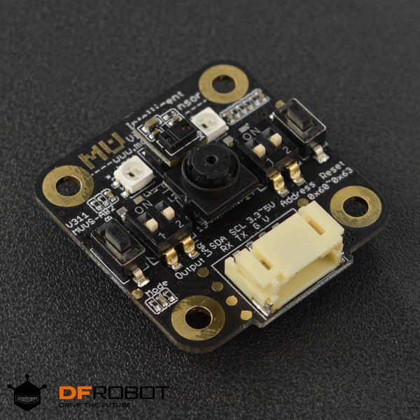
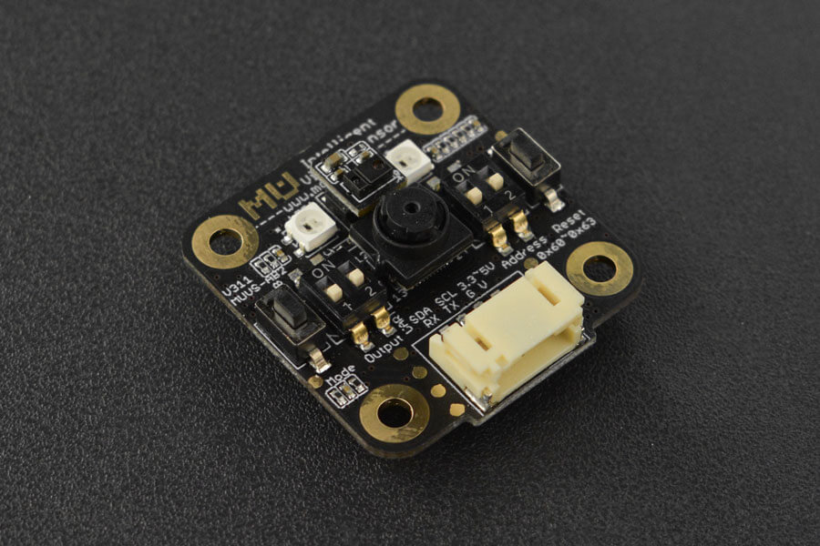
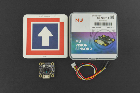
MU Vision Sensor - แท้จาก DFRobot

| รหัสสินค้า | AS00562 |
| หมวดหมู่ | โมดูลวัดสี กล้องและการมองเห็น Camera / Color / Vision |
| ราคา | 3,250.00 บาท |
| สถานะสินค้า | พร้อมส่ง |
| จำนวน | ชิ้น |

รายละเอียดสินค้า
1) รายละเอียดเกี่ยวกับ MU 3 ทั้ง Hardware / Software และ อื่นๆ
2) การเขียนโปรแกรมใช้งาน MU 3 กับ Arduino
3) การเขียนโปรแกรมใช้งาน MU 3 กับ MicroPython
4) การเขียนโปรแกรมใช้งาน MU 3 กับ Mixly
5) การเขียนโปรแกรมใช้งาน MU 3 กับ MakeCode
INTRODUCTION
FEATURES
- Pixy2 detects lines, intersections and small barcodes, intended for line-following robots
- Improved framerate – 60 frames-per-second
- Tracking algorithms have been added to color-based object detection
- Improved and simplified libraries for Arduino, Raspberry Pi and other controllers
- Integrated light source
SPECIFICATION
- Processor: dual-core, 240MHz
- Camera: Omnivision ov7725
- Camera Resolution: 640x480
- Field of View: 90° (Diagonal line)
- 2 LED lights
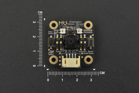
- Dimension: 3.2*3.2*1.2cm/1.26*1.26*0.47”
- Data Output: UART/I2C
- Power Supply: 5V
- Detected Objects:
- People silhouette (above the waist)
- Ball (Ping-pong ball or tennis ball)
- 20 Customized Cards
- Color (Within the detection range, output the color of the designated position or output the position of the designated color)
- Software Library:
- milxy’s library functions and reference programs
- Arduino library functions
- Micro:bit library functions
- Functions In Development:
- WiFi Image Transmission (module as AP)
- Motion Routine Detection(detection of hand movement from top to bottom, left to right, etc,. non-gesture sensing)
- Face recognition
- QR code recognition
DOCUMENTS
SHIPPING LIST- MU Vision Sensor x1
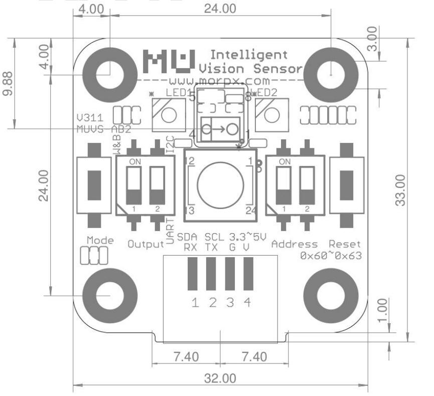
Pinout

| label | Description |
|---|---|
| G | Ground |
| V | Power Input(3.3V or 5V) |
| TX | Serial Port transmitter |
| RX | Serial port receiver |
| SCL | Control line |
| SDA | Data line |
Label Classification
Human Detection
None
Ball Detection
| Label | Objects |
|---|---|
| 1 | Orange Ping-pong ball |
| 2 | Green tennis |
Color Detection
| Label | Color |
|---|---|
| 1 | Black(dark grey) |
| 2 | White(light grey) |
| 3 | Red |
| 4 | Yellow(orange) |
| 5 | Green |
| 6 | Cyan(blue-green) |
| 7 | Blue |
| 8 | Purple |
Card Detection
Pattern Detection
| Label | Pattern |
|---|---|
| 1 | Tick |
| 2 | Cross |
| 3 | Circle |
| 4 | Square |
| 5 | Triangle |
Traffic Sign Card
| Label | Traffic Sign |
|---|---|
| 1 | Go |
| 2 | Turn left |
| 3 | Turn right |
| 4 | Turn around |
| 5 | Stop |
Number Card
| Label | Number |
|---|---|
| 1 | 1 |
| 2 | 2 |
| 3 | 3 |
| 4 | 4 |
| 5 | 5 |
| 6 | 6 |
| 7 | 7 |
| 8 | 8 |
| 9 | 9 |
| 0 | 0 |
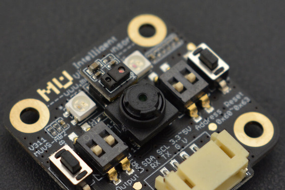
Output Mode and Address Selection
The sensor has two output modes: UART and I2C. Switch the output mode via DIP switch. (The DIP switch marked "Output" is for changing output mode.)
There are four addresses for the sensor to choose from 0x60-0x63. Address in the range is suitable for both output modes. Alter the address via DIP switch. (The DIP switch marked "Address" is for changing address.)
Select Output Mode
A 2-bits DIP switch is used to select signal output type, defined as the chart:
| Bit 1 | Wifi Switch | Bit 2 | Signal Output mode |
|---|---|---|---|
| 0 | Disable Wifi function * | 0 | UART |
| 1 | Enable Wifi function * | 1 | I2C |
- Note 1: * means the function is not supported by the current version.
- Note 2: switch up to set 1, switch down to set 2.
Select Address
A 2-bits DIP switch is used to select device address, defined as the chart:
| Bit 1 | Bit 2 | Address |
|---|---|---|
| 0 | 0 | 0x60 |
| 0 | 1 | 0x61 |
| 1 | 0 | 0x62 |
| 1 | 1 | 0x63 |
- Note 1: MU will respond to the 0x00 broadcast message sent from the host.
- Note 2: switch up to set 1, switch down to set 2.
Module Communication Protocol
Protocol Format
- START: start code, always 0xFF
- LEN: length, the total bytes number from START to END.
- ADDR: device address. Range: 0x60~0x63. 0x00 is the broadcast address and can be received by all device.
- CMD: command code/response code
- DATA: data, refer to instruction code introduction for details
- CHK: checksum, the sum of all bytes from START to DATA
Eg:FF 08 60 01 20 03 8B ED, 8B is the checksum, 0xFF+0x08+0x60+0x01+0x20+0x03 = 0x8B
- END: end code, always 0xED
Response Code
| Correct | Error | Unknown Error | Time-out Error | Checksum Error | Length Error | Command Error | Register Address Error | Parameter Error | Write Error |
|---|---|---|---|---|---|---|---|---|---|
| 0xE0 | 0xE1 | 0xE2 | 0xE3 | 0xE4 | 0xE5 | 0xE6 | 0xE7 | 0xE8 | 0xE9 |
Command Code
| Write Register | Read Register | Data Message | Request Message |
|---|---|---|---|
| 0x01 | 0x02 | 0x11 | 0x12 |
The above are the codes for sending commands. The relevant response code will be returned when the operation fails or succeeds.
How to Use the MU Vision Sensor
Operation Steps
- Set device address;
- Set output mode;
- Version Check;
- Configure hardware settings;
- Configure algorithm settings;
- Read detected result.
Set Device Address
Set the device address of MU sensor via DIP switch, refer to address selection.
Set Output Mode
Set the commincation mode via DIP switch, refer to Output mode selection.
Note: each time you change the output mode and device address, you need to restart the sensor by pressing the reset buttton on the sensor.
Version Check
Read PROTOCOL_VER and FIRMWARE_VER register to check if the firmware is the same as that in the Manual, if not, the register functions and algorithm versions will be different.
Setup Hardware
Set hardware-related registers per the actual application and requirements, mainly including CAMERA_CONF1, LED1, LED2 register.
Setup Vision
Algorithm for each VISION_ID has its own configuration registers. Set VISION_ID before setting the algorithm parameters.

Get results Data via Registers

List of included Vision Algorithms

Detection Result Data:
(1) id: Vision ID
(2) num: the number of detection results [0 or 1]
(3) x: normalized horizontal center coordinate [0...100]
(4) y: normalized vertical center coordinate [0...100]
(5) width: the normalized width of the object [0...100]
(6) height: the normalized height of the object [0...100]
(7) label: classification label number
Arduino Tutorial on UART Mode
Requirements
- Hardware
- UNO x 1
- MU Vision Sensor x 1
- Connectors
- Software
- Arduino IDE
- Download the Library Files and Example Codes

Sample Code
/*
****************************************************
* @brief MU Vision Sensor

* @copyright [DFRobot](https://www.dfrobot.com), 2016
* @copyright GNU Lesser General Public License

* @author [WWZ](Wenzheng.wang@dfrobot.com)
* @version V1.0
* @date 2019-03-11

* GNU Lesser General Public License.
* All above must be included in any redistribution
* ***************************************************
*/

#include <Wire.h>
#include "MuVisionSensor.h"
#include <SoftwareSerial.h>

//#define I2C_MODE
#define SERIAL_MODE
#define MU_ADDRESS 0x60
// change vision type here, VISION_TYPE:VISION_COLOR_DETECT
// VISION_COLOR_RECOGNITION
// VISION_BALL_DETECT
// VISION_BODY_DETECT
// VISION_SHAPE_CARD_DETECT
// VISION_TRAFFIC_CARD_DETECT
// VISION_NUM_CARD_DETECT
//#define VISION_TYPE VISION_BALL_DETECT
//#define VISION_TYPE VISION_BODY_DETECT
//#define VISION_TYPE VISION_SHAPE_CARD_DETECT
#define VISION_TYPE VISION_TRAFFIC_CARD_DETECT
//#define VISION_TYPE VISION_NUM_CARD_DETECT
//#define VISION_TYPE VISION_COLOR_DETECT
//#define VISION_TYPE VISION_COLOR_RECOGNITION

#ifdef SERIAL_MODE
#define TX_PIN 2
#define RX_PIN 3
SoftwareSerial mySerial(RX_PIN, TX_PIN);
#endif
MuVisionSensor Mu(MU_ADDRESS);

void setup() {
// put your setup code here, to run once:
Serial.begin(9600);
delay(500);

#ifdef I2C_MODE
Wire.begin();
Mu.begin(&Wire, kI2CMode);
#elif defined SERIAL_MODE
mySerial.begin(9600);
Mu.begin(&mySerial, kSerialMode);
#endif

Mu.VisionBegin(VISION_TYPE);

if (VISION_TYPE == VISION_COLOR_DETECT
|| VISION_TYPE == VISION_COLOR_RECOGNITION) {
Mu.CameraSetAwb(kLockWhiteBalance); // lock AWB
delay(1000); // waiting for AWB lock.
if (VISION_TYPE == VISION_COLOR_DETECT
|| VISION_TYPE == VISION_COLOR_RECOGNITION) {
Mu.write(VISION_TYPE, kXValue, 50);
Mu.write(VISION_TYPE, kYValue, 50);
Mu.write(VISION_TYPE, kWidthValue, 5);
Mu.write(VISION_TYPE, kHeightValue, 5);
}
}
}

void loop() {
// put your main code here, to run repeatedly:
long time_start = millis();

// read result
if (Mu.GetValue(VISION_TYPE,kStatus)) {
Serial.println("vision detected:");
switch (VISION_TYPE) {
case VISION_BALL_DETECT:
case VISION_BODY_DETECT:
case VISION_SHAPE_CARD_DETECT:
case VISION_TRAFFIC_CARD_DETECT:
case VISION_NUM_CARD_DETECT:
case VISION_COLOR_DETECT:
Serial.print("x = ");
Serial.println(Mu.GetValue(VISION_TYPE, kXValue));
Serial.print("y = ");
Serial.println(Mu.GetValue(VISION_TYPE, kYValue));
Serial.print("width = ");
Serial.println(Mu.GetValue(VISION_TYPE, kWidthValue));
Serial.print("height = ");
Serial.println(Mu.GetValue(VISION_TYPE, kHeightValue));
if (VISION_TYPE != VISION_COLOR_DETECT) {
Serial.print("label = ");
Serial.println(Mu.GetValue(VISION_TYPE, kLabel));
} else {
Serial.print("color = ");
Serial.println(Mu.GetValue(VISION_TYPE, kLabel));
}
break;
case VISION_COLOR_RECOGNITION:
Serial.print("r = ");
Serial.println(Mu.GetValue(VISION_TYPE, kRValue));
Serial.print("g = ");
Serial.println(Mu.GetValue(VISION_TYPE, kGValue));
Serial.print("b = ");
Serial.println(Mu.GetValue(VISION_TYPE, kBValue));
Serial.print("color = ");
Serial.println(Mu.GetValue(VISION_TYPE, kLabel));
break;
default:
break;
}
} else {
Serial.println("vision undetected.");
}
Serial.print("fps = ");
Serial.println(1000/(millis()-time_start));
Serial.println();
}
Output Result: output the RGB value and color label when detecting color; for other objects, returns its coordinate, size and label.
The above program is used to recogniaze traffic cards, and output the center coordinate of the card, the size of the outer edge and the label(the label number under the card). Change the object type at the program #define VISION_TYPE to detect other objects.
Arduino Tutorial on IIC Mode
Requirements
- Hardware
- UNO x 1
- MU Vision Sensor x 1
- Connectors
- Software

Sample Code (Ping-pong ball or tennis ball)
/*
****************************************************
* @brief MU Vision Sensor

* @copyright [DFRobot](https://www.dfrobot.com), 2016
* @copyright GNU Lesser General Public License

* @author [WWZ](Wenzheng.wang@dfrobot.com)
* @version V1.0
* @date 2019-03-11

* GNU Lesser General Public License.
* All above must be included in any redistribution
* ***************************************************
*/

#include <Wire.h>

#define MU_ADDRESS 0x60
#define PROTOCOL_VER 0x03
#define VISION_ID 0x03 // ball

// register define
#define REG_PROTOCOL_VER 0x01
#define REG_LED1_CONF 0x06
#define REG_LED2_CONF 0x07
#define REG_LED_LEVEL 0x08
#define REG_CAMERA_CONF1 0x10
#define REG_FRAME_CNT 0x1F
#define REG_VISION_ID 0x20
#define REG_VISION_CONF1 0x21
#define REG_PARAM_VALUE5 0x29
#define RESULT_NUM 0x34
#define RESULT_DATA1 0x40
#define RESULT_DATA2 0x41
#define RESULT_DATA3 0x42
#define RESULT_DATA4 0x43
#define RESULT_DATA5 0x44
// color
#define MU_COLOR_BLACK 0x01U
#define MU_COLOR_WHITE 0x02U
#define MU_COLOR_RED 0x03U
#define MU_COLOR_YELLOW 0x04U
#define MU_COLOR_GREEN 0x05U
#define MU_COLOR_CYAN 0x06U
#define MU_COLOR_BLUE 0x07U
#define MU_COLOR_PURPLE 0x08U

int i2c_read8(uint8_t reg) {
Wire.beginTransmission(MU_ADDRESS);
Wire.write(reg);
Wire.endTransmission();

Wire.requestFrom(MU_ADDRESS, 1);
return Wire.read();
}
void i2c_write8(const uint8_t reg, const uint8_t value) {
Wire.beginTransmission(MU_ADDRESS);
Wire.write(reg);
Wire.write(value);
Wire.endTransmission();
}

uint8_t reg[][2] = {
{ REG_VISION_ID, VISION_ID }, // set vision type = vision_detect
{ REG_VISION_CONF1, 0x21 }, // vision begin
};
uint8_t frame_count_last = 0;

void setup() {
// put your setup code here, to run once:
Serial.begin(9600);
Wire.begin();
delay(500);

if (i2c_read8(REG_PROTOCOL_VER) == PROTOCOL_VER) {
Serial.println("device initialized.");
} else {
Serial.println("fail to initialize device! Please check protocol version.");
}
for (uint32_t i = 0; i < sizeof(reg)/2; ++i) {
i2c_write8(reg[i][0], reg[i][1]);
}
}

void loop() {
// put your main code here, to run repeatedly:
long time_start = millis();
int frame_count = 0;
// waiting for update
do {
frame_count = i2c_read8(REG_FRAME_CNT);
} while(frame_count == frame_count_last);
frame_count_last = frame_count;

i2c_write8(REG_VISION_ID, VISION_ID);
// read result
if (i2c_read8(RESULT_NUM) > 0) {
Serial.println("ball detected:");
Serial.print("x = ");
Serial.println(i2c_read8(RESULT_DATA1));
Serial.print("y = ");
Serial.println(i2c_read8(RESULT_DATA2));
Serial.print("width = ");
Serial.println(i2c_read8(RESULT_DATA3));
Serial.print("height = ");
Serial.println(i2c_read8(RESULT_DATA4));
Serial.print("label = ");
switch(i2c_read8(RESULT_DATA5)) {
case 1:
Serial.println("Ping-Pong ball");
break;
case 2:
Serial.println("Tennis");
break;
default:
break;
}
} else {
Serial.println("ball undetected.");
}
Serial.print("fps = ");
Serial.println(1000/(millis()-time_start));
Serial.println();
}
Output result: return the center coordinate of the ball, the size of its external border and the label.
Sample Code (Human upper body)
/*
****************************************************
* @brief MU Vision Sensor

* @copyright [DFRobot](https://www.dfrobot.com), 2016
* @copyright GNU Lesser General Public License

* @author [WWZ](Wenzheng.wang@dfrobot.com)
* @version V1.0
* @date 2019-03-11

* GNU Lesser General Public License.
* All above must be included in any redistribution
* ***************************************************
*/

#include <Wire.h>

#define MU_ADDRESS 0x60
#define PROTOCOL_VER 0x03
#define VISION_ID 0x05 // body

// register define
#define REG_PROTOCOL_VER 0x01
#define REG_LED1_CONF 0x06
#define REG_LED2_CONF 0x07
#define REG_LED_LEVEL 0x08
#define REG_CAMERA_CONF1 0x10
#define REG_FRAME_CNT 0x1F
#define REG_VISION_ID 0x20
#define REG_VISION_CONF1 0x21
#define REG_PARAM_VALUE5 0x29
#define RESULT_NUM 0x34
#define RESULT_DATA1 0x40
#define RESULT_DATA2 0x41
#define RESULT_DATA3 0x42
#define RESULT_DATA4 0x43
#define RESULT_DATA5 0x44
// color
#define MU_COLOR_BLACK 0x01U
#define MU_COLOR_WHITE 0x02U
#define MU_COLOR_RED 0x03U
#define MU_COLOR_YELLOW 0x04U
#define MU_COLOR_GREEN 0x05U
#define MU_COLOR_CYAN 0x06U
#define MU_COLOR_BLUE 0x07U
#define MU_COLOR_PURPLE 0x08U

int i2c_read8(uint8_t reg) {
Wire.beginTransmission(MU_ADDRESS);
Wire.write(reg);
Wire.endTransmission();

Wire.requestFrom(MU_ADDRESS, 1);
return Wire.read();
}
void i2c_write8(const uint8_t reg, const uint8_t value) {
Wire.beginTransmission(MU_ADDRESS);
Wire.write(reg);
Wire.write(value);
Wire.endTransmission();
}

uint8_t reg[][2] = {
{ REG_VISION_ID, VISION_ID }, // set vision type = vision_detect
{ REG_VISION_CONF1, 0x21 }, // vision begin
};
uint8_t frame_count_last = 0;

void setup() {
// put your setup code here, to run once:
Serial.begin(9600);
Wire.begin();
delay(500);

if (i2c_read8(REG_PROTOCOL_VER) == PROTOCOL_VER) {
Serial.println("device initialized.");
} else {
Serial.println("fail to initialize device! Please check protocol version.");
}
for (uint32_t i = 0; i < sizeof(reg)/2; ++i) {
i2c_write8(reg[i][0], reg[i][1]);
}
}

void loop() {
// put your main code here, to run repeatedly:
long time_start = millis();
int frame_count = 0;
// waiting for update
do {
frame_count = i2c_read8(REG_FRAME_CNT);
} while(frame_count == frame_count_last);
frame_count_last = frame_count;

i2c_write8(REG_VISION_ID, VISION_ID);
// read result
if (i2c_read8(RESULT_NUM) > 0) {
Serial.println("body detected:");
Serial.print("x = ");
Serial.println(i2c_read8(RESULT_DATA1));
Serial.print("y = ");
Serial.println(i2c_read8(RESULT_DATA2));
Serial.print("width = ");
Serial.println(i2c_read8(RESULT_DATA3));
Serial.print("height = ");
Serial.println(i2c_read8(RESULT_DATA4));
} else {
Serial.println("body undetected.");
}
Serial.print("fps = ");
Serial.println(1000/(millis()-time_start));
Serial.println();
}
Output result: return the center coordinate of the human, the size of the upper body bounding box.
Sample Code (Color)
/*
****************************************************
* @brief MU Vision Sensor

* @copyright [DFRobot](https://www.dfrobot.com), 2016
* @copyright GNU Lesser General Public License

* @author [WWZ](Wenzheng.wang@dfrobot.com)
* @version V1.0
* @date 2019-03-11

* GNU Lesser General Public License.
* All above must be included in any redistribution
* ***************************************************
*/

#include <Wire.h>

#define MU_ADDRESS 0x60
#define PROTOCOL_VER 0x03
#define VISION_ID 0x02

// register define
#define REG_PROTOCOL_VER 0x01
#define REG_LED1_CONF 0x06
#define REG_LED2_CONF 0x07
#define REG_LED_LEVEL 0x08
#define REG_CAMERA_CONF1 0x10
#define REG_FRAME_CNT 0x1F
#define REG_VISION_ID 0x20
#define REG_VISION_CONF1 0x21
#define REG_PARAM_VALUE1 0x25
#define REG_PARAM_VALUE2 0x26
#define REG_PARAM_VALUE3 0x27
#define REG_PARAM_VALUE4 0x28
#define RESULT_NUM 0x34
#define RESULT_DATA1 0x40
#define RESULT_DATA2 0x41
#define RESULT_DATA3 0x42
#define RESULT_DATA5 0x44
// color
#define MU_COLOR_BLACK 0x01U
#define MU_COLOR_WHITE 0x02U
#define MU_COLOR_RED 0x03U
#define MU_COLOR_YELLOW 0x04U
#define MU_COLOR_GREEN 0x05U
#define MU_COLOR_CYAN 0x06U
#define MU_COLOR_BLUE 0x07U
#define MU_COLOR_PURPLE 0x08U

int i2c_read8(uint8_t reg) {
Wire.beginTransmission(MU_ADDRESS);
Wire.write(reg);
Wire.endTransmission();

Wire.requestFrom(MU_ADDRESS, 1);
return Wire.read();
}
void i2c_write8(const uint8_t reg, const uint8_t value) {
Wire.beginTransmission(MU_ADDRESS);
Wire.write(reg);
Wire.write(value);
Wire.endTransmission();
}

uint8_t reg[][2] = {
// { REG_LED_LEVEL, 0x00 }, // LED will be closed automatically in this vision type.
// { REG_LED1_CONF, 0x00 }, // LED1 color
// { REG_LED2_CONF, 0x00 }, // LED2 color
{ REG_CAMERA_CONF1, 0x30 }, // lock AWB
{ REG_VISION_ID, VISION_ID }, // set vision type = vision_recognition
{ REG_PARAM_VALUE1, 50 }, // x
{ REG_PARAM_VALUE2, 50 }, // y
// { REG_PARAM_VALUE3, 5 }, // width
// { REG_PARAM_VALUE4, 5 }, // height
{ REG_VISION_CONF1, 0x21 }, // vision begin
};
uint8_t frame_count_last = 0;

void setup() {
// put your setup code here, to run once:
Serial.begin(9600);
Wire.begin();
delay(500);

if (i2c_read8(REG_PROTOCOL_VER) == PROTOCOL_VER) {
Serial.println("device initialized.");
} else {
Serial.println("fail to initialize device! Please check protocol version.");
}
for (uint32_t i = 0; i < sizeof(reg)/2; ++i) {
i2c_write8(reg[i][0], reg[i][1]);
}
delay(1000); // waiting for AWB lock.
}

void loop() {
// put your main code here, to run repeatedly:
long time_start = millis();
int frame_count = 0;
// waiting for update
do {
frame_count = i2c_read8(REG_FRAME_CNT);
} while(frame_count == frame_count_last);
frame_count_last = frame_count;

i2c_write8(REG_VISION_ID, VISION_ID);
// read result
if (i2c_read8(RESULT_NUM) > 0) {
Serial.println("color detected:");
Serial.print("color = (");
Serial.print(i2c_read8(RESULT_DATA1));
Serial.print(",");
Serial.print(i2c_read8(RESULT_DATA2));
Serial.print(",");
Serial.print(i2c_read8(RESULT_DATA3));
Serial.print(")\nlabel = ");
switch (i2c_read8(RESULT_DATA5)) {
case 0:
Serial.println("unknow color");
break;
case 1:
Serial.println("black");
break;
case 2:
Serial.println("white");
break;
case 3:
Serial.println("red");
break;
case 4:
Serial.println("yellow");
break;
case 5:
Serial.println("green");
break;
case 6:
Serial.println("cyan");
break;
case 7:
Serial.println("blue");
break;
case 8:
Serial.println("violet");
break;
default:
break;
}
} else {
Serial.println("color undetected.");
}
Serial.print("fps = ");
Serial.println(1000/(millis()-time_start));
Serial.println();
}
Output: return the RGB channels average value (Rang 0~255) and color label.
Sample Code (20 Customized cards)
/*
****************************************************
* @brief MU Vision Sensor

* @copyright [DFRobot](https://www.dfrobot.com), 2016
* @copyright GNU Lesser General Public License

* @author [WWZ](Wenzheng.wang@dfrobot.com)
* @version V1.0
* @date 2019-03-11

* GNU Lesser General Public License.
* All above must be included in any redistribution
* ***************************************************
*/

#include <Wire.h>

#define MU_ADDRESS 0x60
#define PROTOCOL_VER 0x03
#define VISION_ID 0x06 // shape card
//#define VISION_ID 0x07 // traffic card
//#define VISION_ID 0x08 // number card

// register define
#define REG_PROTOCOL_VER 0x01
#define REG_LED1_CONF 0x06
#define REG_LED2_CONF 0x07
#define REG_LED_LEVEL 0x08
#define REG_CAMERA_CONF1 0x10
#define REG_FRAME_CNT 0x1F
#define REG_VISION_ID 0x20
#define REG_VISION_CONF1 0x21
#define REG_PARAM_VALUE5 0x29
#define RESULT_NUM 0x34
#define RESULT_DATA1 0x40
#define RESULT_DATA2 0x41
#define RESULT_DATA3 0x42
#define RESULT_DATA4 0x43
#define RESULT_DATA5 0x44
// color
#define MU_COLOR_BLACK 0x01U
#define MU_COLOR_WHITE 0x02U
#define MU_COLOR_RED 0x03U
#define MU_COLOR_YELLOW 0x04U
#define MU_COLOR_GREEN 0x05U
#define MU_COLOR_CYAN 0x06U
#define MU_COLOR_BLUE 0x07U
#define MU_COLOR_PURPLE 0x08U

int i2c_read8(uint8_t reg) {
Wire.beginTransmission(MU_ADDRESS);
Wire.write(reg);
Wire.endTransmission();

Wire.requestFrom(MU_ADDRESS, 1);
return Wire.read();
}
void i2c_write8(const uint8_t reg, const uint8_t value) {
Wire.beginTransmission(MU_ADDRESS);
Wire.write(reg);
Wire.write(value);
Wire.endTransmission();
}

uint8_t reg[][2] = {
{ REG_VISION_ID, VISION_ID }, // set vision type = vision_detect
{ REG_VISION_CONF1, 0x21 }, // vision begin
};
uint8_t frame_count_last = 0;

void setup() {
// put your setup code here, to run once:
Serial.begin(9600);
Wire.begin();
delay(500);

if (i2c_read8(REG_PROTOCOL_VER) == PROTOCOL_VER) {
Serial.println("device initialized.");
} else {
Serial.println("fail to initialize device! Please check protocol version.");
}
for (uint32_t i = 0; i < sizeof(reg)/2; ++i) {
i2c_write8(reg[i][0], reg[i][1]);
}
}

void loop() {
// put your main code here, to run repeatedly:
long time_start = millis();
int frame_count = 0;
// waiting for update
do {
frame_count = i2c_read8(REG_FRAME_CNT);
} while(frame_count == frame_count_last);
frame_count_last = frame_count;

i2c_write8(REG_VISION_ID, VISION_ID);
// read result
if (i2c_read8(RESULT_NUM) > 0) {
Serial.println("card detected:");
Serial.print("x = ");
Serial.println(i2c_read8(RESULT_DATA1));
Serial.print("y = ");
Serial.println(i2c_read8(RESULT_DATA2));
Serial.print("width = ");
Serial.println(i2c_read8(RESULT_DATA3));
Serial.print("height = ");
Serial.println(i2c_read8(RESULT_DATA4));
Serial.print("label = ");
Serial.println(i2c_read8(RESULT_DATA5));
} else {
Serial.println("card undetected.");
}
Serial.print("fps = ");
Serial.println(1000/(millis()-time_start));
Serial.println();
}
Output result: return the center coordinate of the card, its outer size and label.
Mind+ Graphical Programming
1.Download and install Mind+ V1.5.6 above. Download Address: http://mindplus.cc. Tutorial: Mind+ basic tutorial.
2.Switch to "Offline" mode.
3.Click extension to load a controller like "micro:bit" or "mPython", and load the SEN0314 MU vision sensor.


4.Select the related product, and programming. Take micro:bit as an example:

5.Connect the device to the computer and upload the codes to your device.
6.Let the sensor to detect the number card, then you can see the result on micro:bit. (Switch Output DIP 1 down, 2 up; Switch Address DIP 1 down, 2 down.)

วิธีการชำระเงิน
ชำระเงินค่าสินค้าโดยการโอนเงินเข้าบัญชีธนาคาร KBANK, SCB, BBL,TMB
กรุณาเก็บหลักฐานการโอนเงินของท่านไว้เพื่อแจ้งการชำระเงินด้วยค่ะ
ท่านสามารถแจ้งการชำระเงินผ่านระบบอัตโนมัติได้โดย Click Link ข้างล่างค่ะ
https://www.arduitronics.com/informpayment
ชำระเงินผ่านธนาคาร


@rfm0967y
ติดต่อสอบถาม
Join เป็นสมาชิกร้านค้า
MEMBER
