
Gravity: KnowFlow Basic Kit - A DIY Water Monitoring Basic Kit (แท้จาก DFRobot)


| รหัสสินค้า | AS20317 |
| หมวดหมู่ | วัดสภาพแวดล้อมและแก๊ส Environmental / Gas |
| ราคา | 9,850.00 บาท |
| สถานะสินค้า | พร้อมส่ง |
| จำนวน | ชิ้น |

รายละเอียดสินค้า
หมายเหตุ:
แนะนำให้ติดตั้งระบบ KnowFlow ในกล่องกันน้ำขนาด 200mmx150mmx75mm และใช้แผ่นอะคริลิกเพื่อยึดติด sensors และ module ต่างๆ โดย Layout ของการวางบอร์ดและโมดูลต่างๆในกล่อง รวมทั้งการเจาะอะคริลิกสามารถเข้าไปดูได้ใน GiHub
ตัวอย่างการนำ KnowFlow ไปใช้จริง
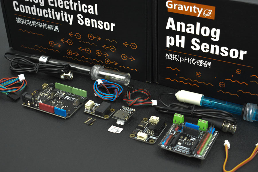
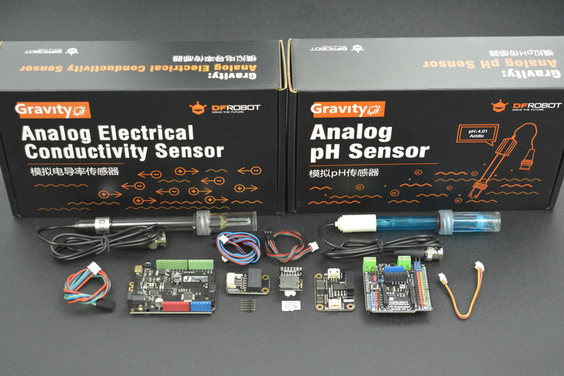
- บอร์ด Bluno x1
- Gravity: Analog pH Sensor / Meter Kit For Arduino x1
- Gravity: Analog Electrical Conductivity Sensor / Meter For Arduino x1
- Gravity: IO Expansion Shield for Arduino V7.1 x1
- Gravity: I2C SD2405 RTC Module x1
- MicroSD card module for Arduino x1
- Gravity: Analog Signal Isolator x1
- SD/MicroSD Memory Card (16GB Class10 SDHC with Adapter) x1
KnowFlow AWM (Automatic Water Monitor) is the first kit for Open-Source Science in the KnowFlow team. KnowFlow team comes from the NGO GreenSeed Organization. We are going to build a low-cost water monitor for the people who join the course. Then we found that a lot of people need the water monitor, so we release all the things to help people make themselves water monitors.
Using the water monitor, you can find the water quality in real-time, also you can store the data into the TF card, analyze the data. It can be used on environmental study, pollution sourcing, and teaching, etc.
KnowFlow team focuses on the solution of environmental and agriculture problems. We can provide the best tool by using hardware, software, courses, and cloud technology. We can support scientists, students, citizens, and environmentalists to using Digital Technology for application in the environment and agriculture. We want to promote the development of Open Science and Open innovation through these efforts.
KnowFlow Kits is using the DFRobot Gravity Sensor series. Gravity Sensor series are easy to use and high compatibility. If you do not care about the code, you can just upload the sketch into the Bluno board without any coding job. After that, you can find that the data is storing in the TF card.
KnowFlow can be powered by a power bank or Li-po battery. For the advanced function, you may add an ORP sensor, and Dissolve Oxygen sensor in your kit.
You can find the course video which is made by GreenSeed and MushroomCloud maker space.
Attention
As a basic version of KnowFlow, this Kit is just INCLUDE pH and EC sensors. You may check Gravity: Waterproof DS18B20 Sensor Kit to enable temperature measuring function.
We will recommend using a 200mmx150mmx75mm waterproof case and an acrylic plate to mount KnowFlow sensors. You can find the dwg in GitHub.
FEATURES
- pH, EC auto record
- Micro-SD Local storage
- Extensible design
- plug and play
- Bluetooth built-in
SPECIFICATION
- Bluno Microcontroller: *On-board BLE chip: TI CC2540
- Wireless Programming via BLE
- Support AT command to config the BLE
- Transparent communication through Serial
- Upgrade BLE firmware easily
- DC Supply: USB Powered or External 7V~12V DC
- Microcontroller: Atmega328p
- Bootloader: Arduino Uno (disconnect any BLE device before uploading a new sketch)
- Compatible with the Arduino Uno pin mapping
- Size: 60mm * 53mm (2.36"*2.08")
- Weight: 30g
- pH sensor:
- Module Power: 5.00V
- Module Size: 43 x 32mm (1.69x1.26")
- Measuring Range:0 - 14PH
- Accuracy: ± 0.1pH (25 ℃)
- Response Time: ≤ 1min
- pH Sensor with BNC Connector
- pH2.0 Interface (3 foot patch )
- Gain Adjustment Potentiometer
- Power Indicator LED
- EC sensor
- Operating Voltage: +5.00 V
- PCB Size: 45 × 32mm(1.77x1.26")
- Measuring Range: 1ms/cm -- 20ms/cm
- Operating Temperature: 5 - 40 ℃
- Accuracy: ±10% F.S (using Arduino 10 bits ADC)
- PH2.0 Interface (3-pin SMD)
- Conductivity Electrode (Electrode Constant K = 1,BNC connector)
- Cable Length of the Electrode: about 60cm(23.62")
- Power Indicator
- Analog Signal Isolator
- Operating Voltage: 5.0V
- Response Time: 4 seconds (Typ)
- Analog Error (both ends): ± 20mV (Typ)
- Interface Type: PH2.0-3P
- No load Current: 75mA
- Dimension: 42 * 32mm / 1.65 * 1.26 inch
- Non-isolated Terminal (Arduino Side)
- Supply Voltage: 5.0 ± 0.1V
- Analog Output: 0 ~ 5.0V
- Isolated Terminal (Sensor Side)
- Output Voltage: 5.0 ± 0.2V
- Analog Input: 0 ~ 5.0V
DOCUMENTS
- Github
- tutorial
- GreenSeed online courses
- application: Water Quality Investigation on African Tea Garden
- application: Willow Creek Water Quality Monitoring
- Analog Signal Isolator
SHIPPING LIST
- Bluno x1
- Gravity: Analog pH Sensor / Meter Kit For Arduino x1
- Gravity: Analog Electrical Conductivity Sensor / Meter For Arduino x1
- Gravity: IO Expansion Shield for Arduino V7.1 x1
- Gravity: I2C SD2405 RTC Module x1
- MicroSD card module for Arduino x1
- Gravity: Analog Signal Isolator x1
- SD/MicroSD Memory Card (16GB Class10 SDHC with Adapter) x1
Background in environmental investigation NGO, my knowledge on electronic development is very limited. Hopefully this document could help people like me to easily understand and replicate such a tool.
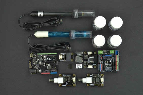
KnowFlow is the name of this water quality monitoring device, based on Arduino Uno. It can automatically monitor 5 parameters of water: pH, Temperature, Dissolved Oxygen, Electronic Conductivity, ORP.
Currently, KnowFlow is powered by a 7.4V lipo battery, the data is stored in a SD card. The field test will be described in a separate research note.
DFRobot produces all the electronic components except for DO, which is produced by Atlas Scientific (btw, all the DFRobot's products are open source), most of the materials I listed are made by them.
Prepare the materials

- Central Control Unit: Arduino Uno (DFRobot Bluno in this case) and Expansion Shield (DFRobot Expansion Shield V7.1 in this case)
- Water Sensors: pH (pH probe and pH circuit board); EC (EC probe and EC circuit board); ORP (ORP probe and ORP circuit board); Temperature (temperature probe and temperature circuit board); Dissolved Oxygen (DO probe, BNC and circuit board); real time clock circuit board
- Data Storage: Micro-SD module, Micro SD card
- Fit and fix: mounting plate, water proof box( 200mm_150mm_75mm), water proof joint
- Other parts: Cables (Wires), bread board, bolts and nuts, screws, battery, double-sided adhesive, write on tape, small wrench, spiral cable wrap
The size, modal, drawings, and other specifications of the materials can be found here at google docs.
Software
- Download Arduino IDE
- Download Knowflow code from KnowFlow github
- find "WaterMonitor.ino" from the downloaded file, open it with Arduino IDE
- Connect your Arduino Uno board, in menus, select "Tools - Board: Arduino Uno", and "Ports - /dev/cu.usb..."
- click "Verify", than "Upload" the software to your board.
Hardware
We need to connect all the sensors, MicroSD card module to the Arduino, then fixed it to the plate and the waterproof box, connected to the power supply.
Those who are familiar with the Arduino could directly read code annotation
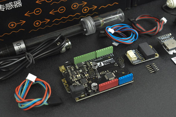
1. Connect the circuit board and other modules to the Arduino expansion (I / O Expansion Shield V7.1)
- Connect EC: Plug one end of the "orange-red-black" cable to the EC circuit board, other end to the IN terminal of the isolation module. Plug the white end of the "blue-red-black" cable to the OUT terminal of the isolation module, the black end to Analog port A1, note the color should be matched.


- Connect the pH: Plug the white end of the "blue-red-black" cable to the pH data transfer board, the black end to port A2.

- Connect ORP: Like EC, Plug one end of the "orange-red-black" cable to the EC data adapter and the other end to the IN terminal of the isolation module. Plug the white end of the "blue-red-black" cable to the OUT terminal of the isolation module, and the black end to the A3

- Connection temperature: Plug the white end of the "green-red-black" cable to the Plugable Terminal V2, and the black end to Digital Port D5

- Connect the dissolved oxygen DO: The connection of the dissolved oxygen is bit complicated. Using four wires and breadboard to connect DO to the serial port (connection principle is GND-GND, VCC-VCC, TX-RX, RX-TX)


Note! Very important! Each time you re-upload the program to Arduino, you need to pull out the Rx (0) Tx (1) cable, and re-plug it after uploading. Otherwise it can not be programmed successfully.
- Connect the Real Time Clock (RTC) module: Plug the white end of the "blue-green-red-black" cable to RTC, and the black end to the blue I2C interface (you might need to wrap the line in case it's too long)
- Connect the MicroSD card module to the blue SD card slot (note the direction) and insert the Micro SD card

Great!!! All sensors are connected!
Tips: You can use the write-on tape to mark different sensors to avoid confounding, and wrap the analog cables and DO cables respectively to avoid clutter.
2. Place the mounting plate to the waterproof box (The drawing of the mounting plate is here at GitHub )
Find the mounting plate, bolts and screws, install the hexagonal column to the small holes. The nylon column is mounted on the front of the board and the nut is mounted on the opposite side. Among which, the 4 Arduino fixing hole requires 6mm nylon column, which the rest requires 4mm nylon columns. You can use a small wrench to help tighten.


Use two 4mm screws to secure the board in the waterproof box. (Some waterproof box might conflict with the lower right column, it can be removed in this case)

3. Attach the electronic components to the mounting plate
- Since the DO module is more difficult to install, so we should install it first. (it can also be soldered). Attach the double-sided adhesive tape under the DO breadboard. Pass BNC interface from the circuit board through the hole, adhere the breadboard.

- Fix Arduino Uno, place the Arduino expansion board.

- Pass the BNC of ORP's circuit board though the rightmost hole of the waterproof box, fix it to the mounting plate with screws, install EC and pH in the same way.

- Adhere the two isolating modules to the top right of the mounting plate by tape.

- Fix RTC

- Now, only left temperature module. Tighten the waterproof connector to the round hole outlet of the temperature probe


- Then, the temperature probe has a bare end of the line, followed by waterproof connector cover and round hole,

- There are three "gates" in the front of the temperature signal adapter board. Press the button above, and the "gate" will open. Plug the yellow wire in the A gate, the red wire to B gate, black wire to C gate. Try to pull out the three wires respectively to make sure there're fastened after plugging in.

- Use a screw to secure the temperature signal adapter board to the board and tighten the waterproof connector nut on the housing.

- In-box part is completed, now connect the battery to test whether the installation is correct. If the light turns on, it means that the circuit is normal.

- Close the box and connect each probes.

Done!

The field test of this device will be written in a separate research note.

วิธีการชำระเงิน
ชำระเงินค่าสินค้าโดยการโอนเงินเข้าบัญชีธนาคาร KBANK, SCB, BBL,TMB
กรุณาเก็บหลักฐานการโอนเงินของท่านไว้เพื่อแจ้งการชำระเงินด้วยค่ะ
ท่านสามารถแจ้งการชำระเงินผ่านระบบอัตโนมัติได้โดย Click Link ข้างล่างค่ะ
https://www.arduitronics.com/informpayment
ชำระเงินผ่านธนาคาร


@rfm0967y
ติดต่อสอบถาม
Join เป็นสมาชิกร้านค้า
MEMBER
