
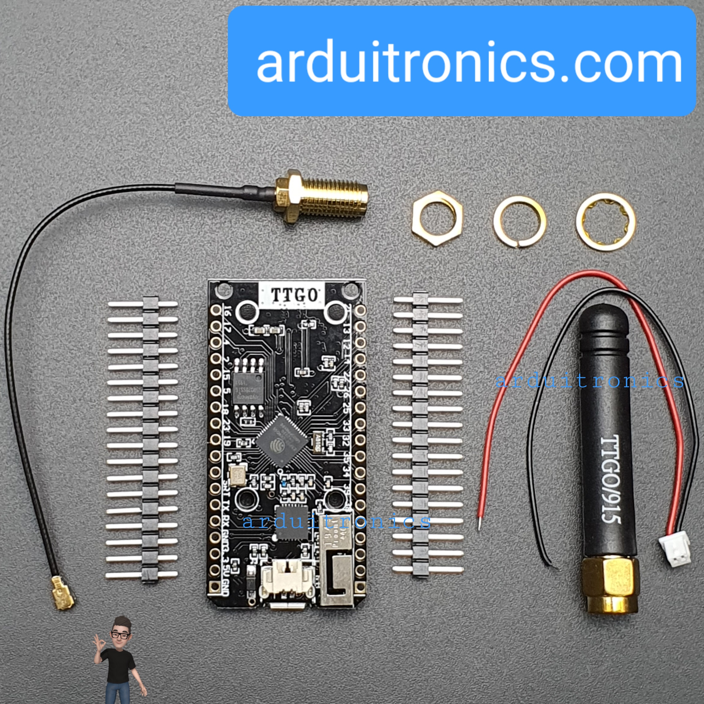
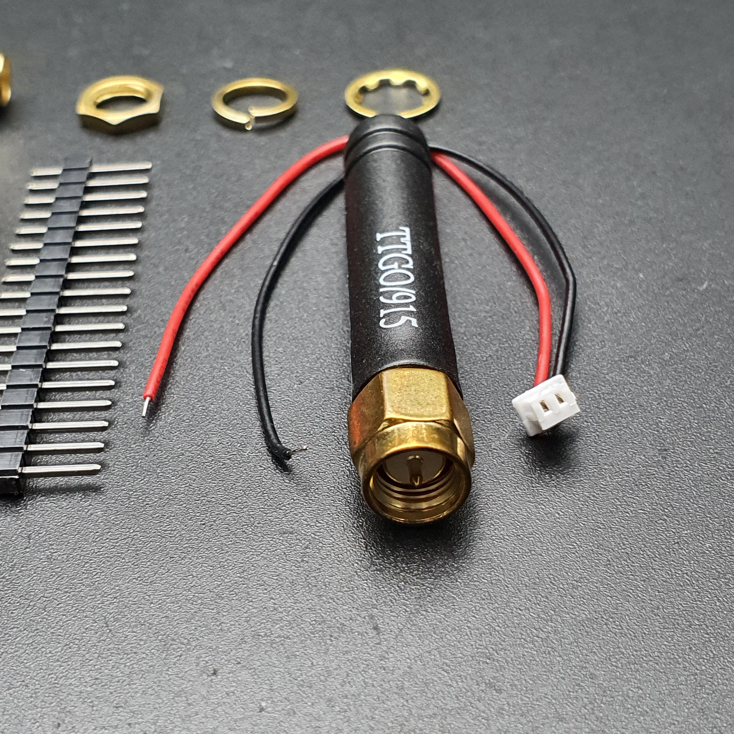
TTGO SX1276 LoRa32 915MHz (CH9120X) + ESP32 + Antenna + Cable
| รหัสสินค้า | BA00137 |
| หมวดหมู่ | LoRa / LoRa+WiFi |
| ราคา | 985.00 บาท |
| สถานะสินค้า | พร้อมส่ง |
| จำนวน | ชิ้น |

รายละเอียดสินค้า
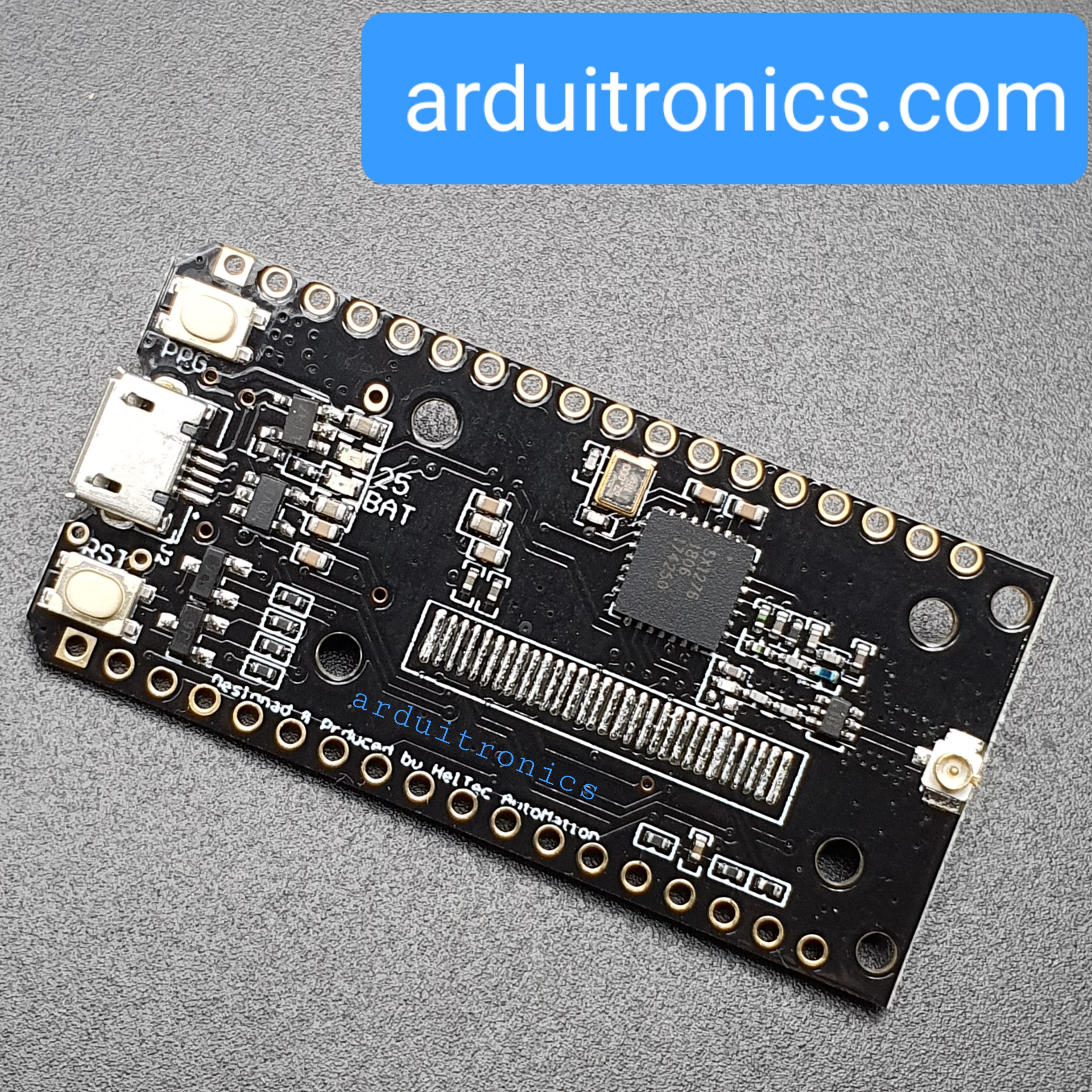
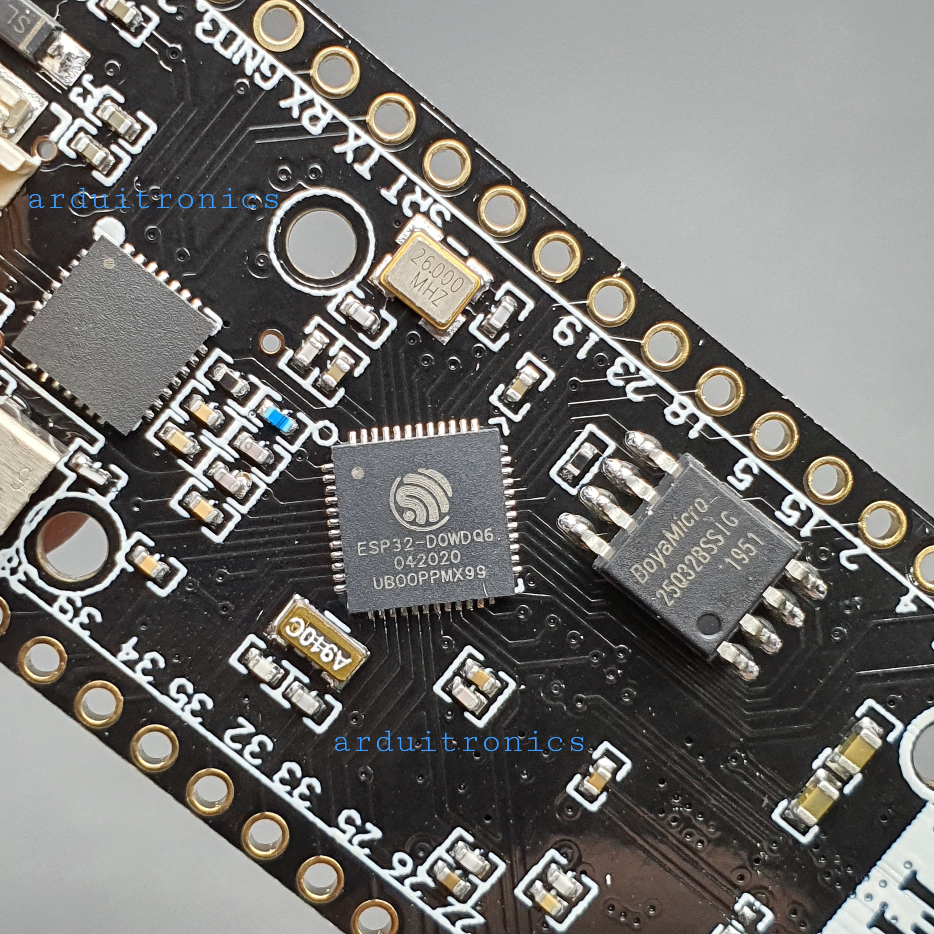
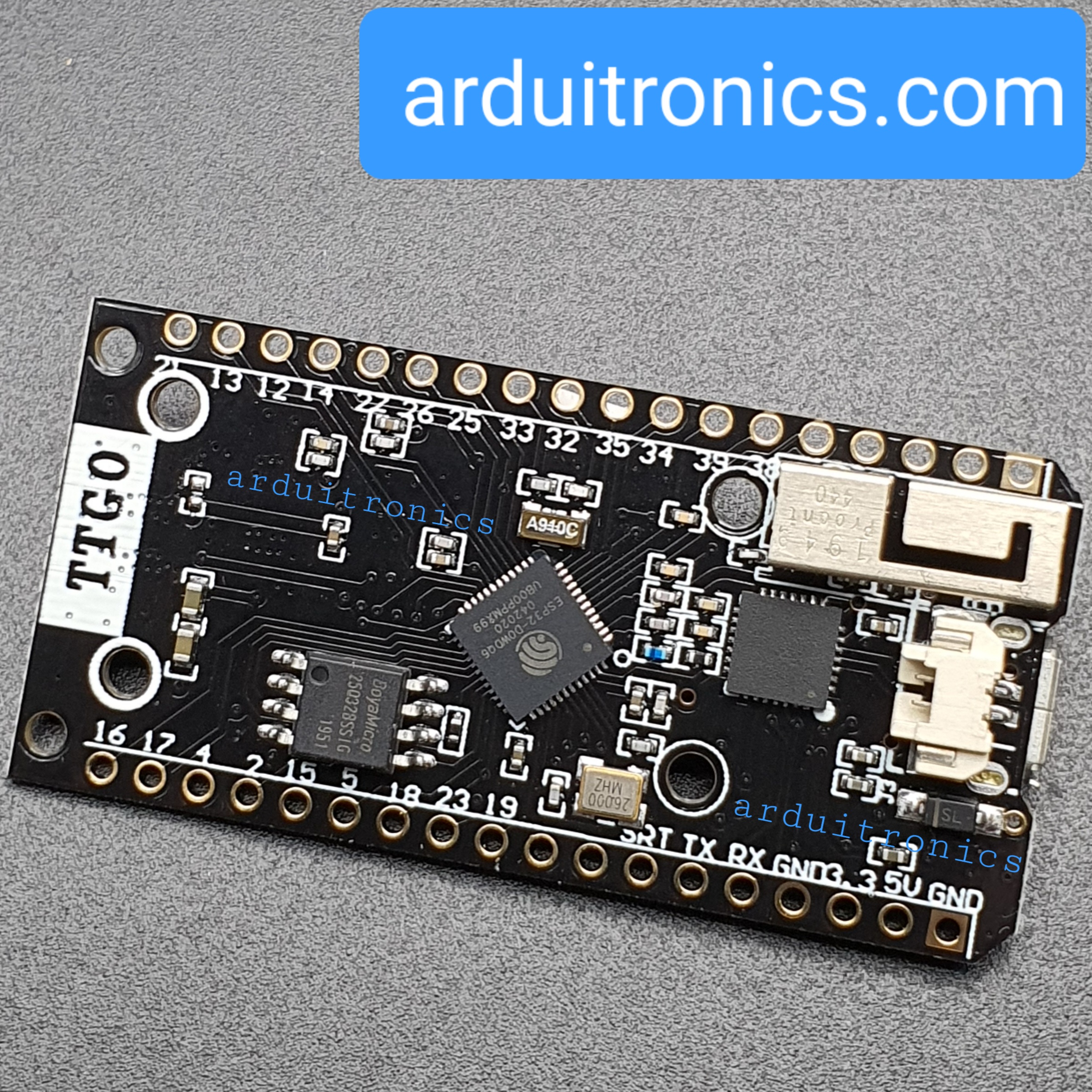
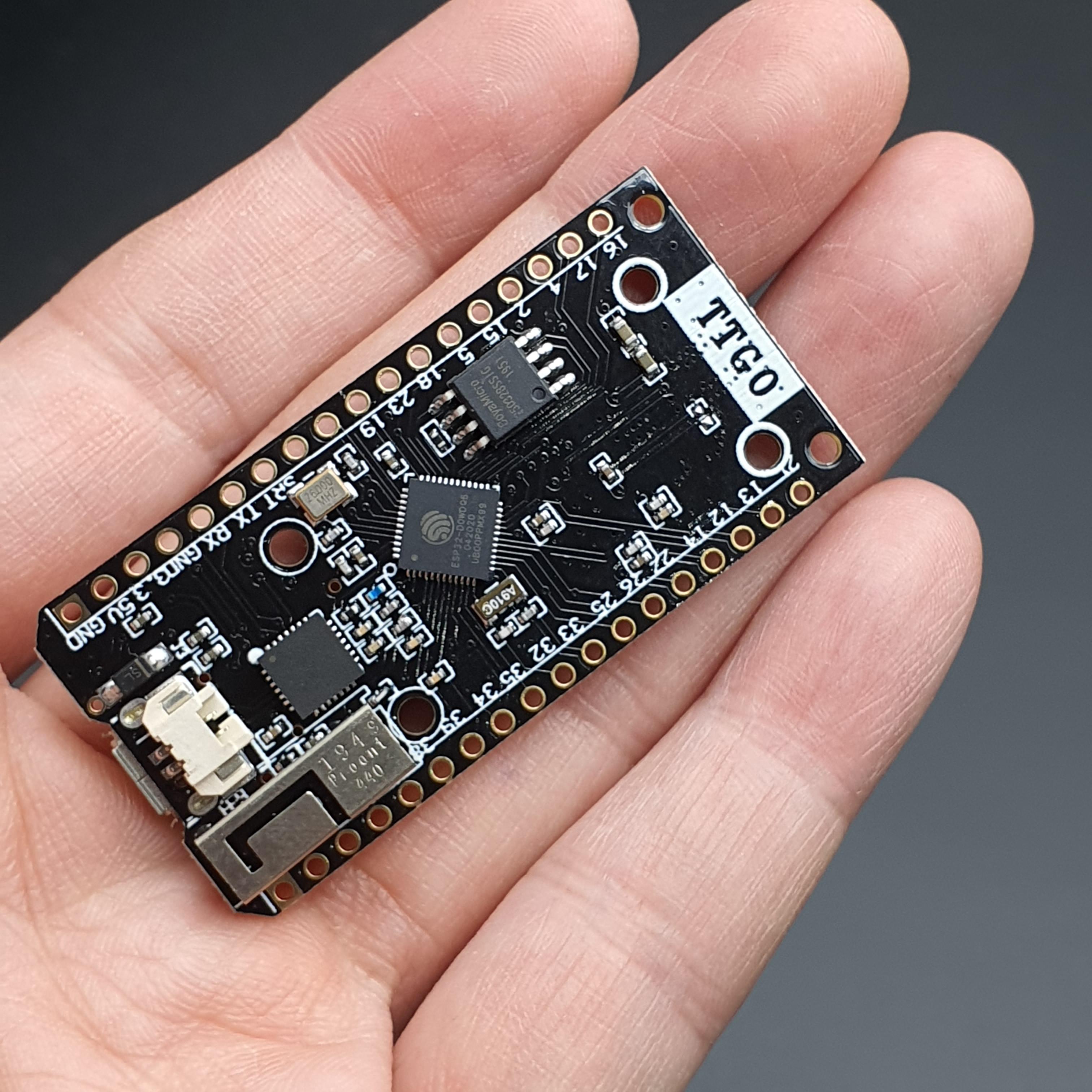
TTGO LoRa32 SX1276
The following figure shows the TTGO LoRa32 board pinout.

The OLED displays communicates using I2C communication protocol. It is internally
connected to the ESP32 on the following pins:
| OLED (built-in) | ESP32 |
| SDA | GPIO 4 |
| SCL | GPIO 15 |
| RST | GPIO 16 |
The SX1276 LoRa chip communicates via SPI communication protocol, and it is internally connected to the ESP32 on the following GPIOs:
| SX1276 LoRa | ESP32 |
| MISO | GPIO 19 |
| MOSI | GPIO 27 |
| SCK | GPIO 5 |
| CS | GPIO 18 |
| IRQ | GPIO 26 |
| RST | GPIO 14 |
Install ESP32 Boards on Arduino IDE
To program the TTGO LoRa32 board, we’ll use Arduino IDE. So, you must have Arduino IDE installed as well as the ESP32 add-on. Follow the next guide to install the ESP32 package on Arduino IDE, if you haven’t already:
I
Installing LoRa Library
There are several libraries available to easily send and receive LoRa packets with the ESP32. In this example we’ll be using the arduino-LoRa library by sandeep mistry.
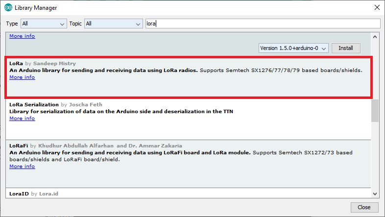
Open your Arduino IDE, and go to Sketch > Include Library > Manage Libraries and search for “LoRa“. Select the LoRa library highlighted in the figure below, and install it.
After installing the libraries, restart your Arduino IDE.
LoRa Sender Sketch
Copy the following code to your Arduino IDE. This code sends a “hello” message followed by a counter via LoRa every 10 seconds. It also displays the counter on the OLED display.
/*********
Rui Santos
Complete project details at https://RandomNerdTutorials.com/ttgo-lora32-sx1276-arduino-ide/
*********/

//Libraries for LoRa
#include
#include

//Libraries for OLED Display
#include
#include
#include

//define the pins used by the LoRa transceiver module
#define SCK 5
#define MISO 19
#define MOSI 27
#define SS 18
#define RST 14
#define DIO0 26

//433E6 for Asia
//866E6 for Europe
//915E6 for North America
#define BAND 866E6

//OLED pins
#define OLED_SDA 4
#define OLED_SCL 15
#define OLED_RST 16
#define SCREEN_WIDTH 128 // OLED display width, in pixels
#define SCREEN_HEIGHT 64 // OLED display height, in pixels

//packet counter
int counter = 0;

Adafruit_SSD1306 display(SCREEN_WIDTH, SCREEN_HEIGHT, &Wire, OLED_RST);

void setup() {

//reset OLED display via software
pinMode(OLED_RST, OUTPUT);
digitalWrite(OLED_RST, LOW);
delay(20);
digitalWrite(OLED_RST, HIGH);

//initialize OLED
Wire.begin(OLED_SDA, OLED_SCL);
if(!display.begin(SSD1306_SWITCHCAPVCC, 0x3c, false, false)) { // Address 0x3C for 128x32
Serial.println(F("SSD1306 allocation failed"));
for(;;); // Don't proceed, loop forever
}

display.clearDisplay();
display.setTextColor(WHITE);
display.setTextSize(1);
display.setCursor(0,0);
display.print("LORA SENDER ");
display.display();

//initialize Serial Monitor
Serial.begin(115200);

Serial.println("LoRa Sender Test");

//SPI LoRa pins
SPI.begin(SCK, MISO, MOSI, SS);
//setup LoRa transceiver module
LoRa.setPins(SS, RST, DIO0);

if (!LoRa.begin(BAND)) {
Serial.println("Starting LoRa failed!");
while (1);
}
Serial.println("LoRa Initializing OK!");
display.setCursor(0,10);
display.print("LoRa Initializing OK!");
display.display();
delay(2000);
}

void loop() {

Serial.print("Sending packet: ");
Serial.println(counter);

//Send LoRa packet to receiver
LoRa.beginPacket();
LoRa.print("hello ");
LoRa.print(counter);
LoRa.endPacket();

display.clearDisplay();
display.setCursor(0,0);
display.println("LORA SENDER");
display.setCursor(0,20);
display.setTextSize(1);
display.print("LoRa packet sent.");
display.setCursor(0,30);
display.print("Counter:");
display.setCursor(50,30);
display.print(counter);
display.display();

counter++;

delay(10000);
}
How the code works
Start by including the libraries to interact with the LoRa chip.
#include
#include
Then, include the libraries to interface with the I2C OLED display.
#include
#include
#include
Define the pins used by the LoRa transceiver module:
#define SCK 5
#define MISO 19
#define MOSI 27
#define SS 18
#define RST 14
#define DIO0 26
Select the LoRa frequency:
#define BAND 866E6Define the OLED pins.
#define OLED_SDA 4
#define OLED_SCL 15
#define OLED_RST 16
Define the OLED size.
#define SCREEN_WIDTH 128 // OLED display width, in pixels
#define SCREEN_HEIGHT 64 // OLED display height, in pixels
Create a counter variable to keep track of the number of LoRa packets sent.
int counter = 0;Create an Adafruit_SSD1306 object called display.
Adafruit_SSD1306 display(SCREEN_WIDTH, SCREEN_HEIGHT, &Wire, OLED_RST);setup()
In the setup(), to start using the OLED you need to do a manual reset via software using the RST pin. To do this reset, you need to declare the RST pin as an output, set it to LOW for a few milliseconds and then, set it to HIGH again.
pinMode(OLED_RST, OUTPUT);
digitalWrite(OLED_RST, LOW);
delay(20);
digitalWrite(OLED_RST, HIGH);
Start an I2C communication using the defined OLED_SDA and OLED_SCL pins using Wire.begin().
Wire.begin(OLED_SDA, OLED_SCL);After that, initialize the display with the following parameters. The parameters set as false ensure that the library doesn’t use the default I2C pins and use the pins defined in the code (GPIO 4 and GPIO 15).
if(!display.begin(SSD1306_SWITCHCAPVCC, 0x3c, false, false)) { // Address 0x3C for 128x32
Serial.println(F("SSD1306 allocation failed"));
for(;;); // Don't proceed, loop forever
}
Then, you can use the methods from the Adafruit library to interact with the OLED display. To learn more you can read our tutorial about the I2C OLED display with the ESP32.
Write the message “LORA SENDER” to the display.
display.clearDisplay();
display.setTextColor(WHITE);
display.setTextSize(1);
display.setCursor(0,0);
display.print("LORA SENDER ");
display.display();
Initialize the serial monitor for debugging purposes.
Serial.begin(115200);
Serial.println("LoRa Sender Test");
Define the SPI pins used by the LoRa chip.
SPI.begin(SCK, MISO, MOSI, SS);And set up the LoRa transceiver module.
LoRa.setPins(SS, RST, DIO0);Finally, initialize the LoRa transceiver module using the begin() method on the LoRa object and pass the frequency as argument.
if (!LoRa.begin(BAND)) {
Serial.println("Starting LoRa failed!");
while (1);
}
If we succeed in initializing the display, we write a success message on the OLED display.
display.setCursor(0,10);
display.print("LoRa Initializing OK!");
display.display();
loop()
In the loop() is where we’ll send the packets. You initialize a packet with the beginPacket() method.
LoRa.beginPacket();You write data into the packet using the print() method. As you can see in the following two lines, we’re sending a hello message followed by the counter.
LoRa.print("hello ");
LoRa.print(counter);
Then, close the packet with the endPacket() method.
LoRa.endPacket();Next, write the counter on the OLED display
display.clearDisplay();
display.setCursor(0,0);
display.println("LORA SENDER");
display.setCursor(0,20);
display.setTextSize(1);
display.print("LoRa packet sent.");
display.setCursor(0,30);
display.print("Counter:");
display.setCursor(50,30);
display.print(counter);
display.display();
After this, the counter message is incremented by one in every loop, which happens every 10 seconds.
counter++;
delay(10000);
Testing the LoRa Sender
Upload the code to your board. You need to select the right board and COM port you’re using.
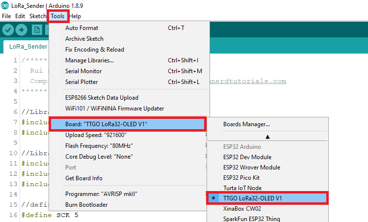
To select the board, in the Arduino IDE, go to Tools > Board and select the TTGO LoRa32-OLED V1 board.
After uploading the code to your board, it should start sending LoRa packe

วิธีการชำระเงิน
ชำระเงินค่าสินค้าโดยการโอนเงินเข้าบัญชีธนาคาร KBANK, SCB, BBL,TMB
กรุณาเก็บหลักฐานการโอนเงินของท่านไว้เพื่อแจ้งการชำระเงินด้วยค่ะ
ท่านสามารถแจ้งการชำระเงินผ่านระบบอัตโนมัติได้โดย Click Link ข้างล่างค่ะ
https://www.arduitronics.com/informpayment
ชำระเงินผ่านธนาคาร


@rfm0967y
ติดต่อสอบถาม
Join เป็นสมาชิกร้านค้า
MEMBER
