
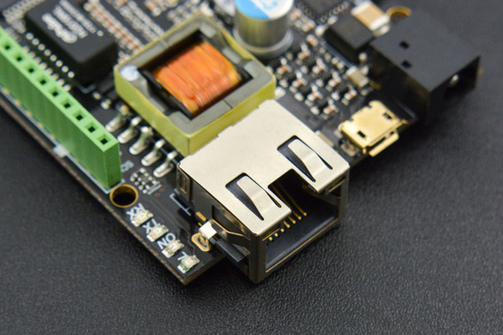
W5500 Ethernet with POE IOT Board (Arduino Compatible) - ของแท้ DFRobot
| รหัสสินค้า | SA30011 |
| หมวดหมู่ | Arduino Shields |
| ราคา | 2,185.00 บาท |
| สถานะสินค้า | พร้อมส่ง |
| จำนวน | 1 |

รายละเอียดสินค้า
ดูตัวอย่างการใช้งานพร้อง code ตัวอย่างด้านล่างของหน้านี้
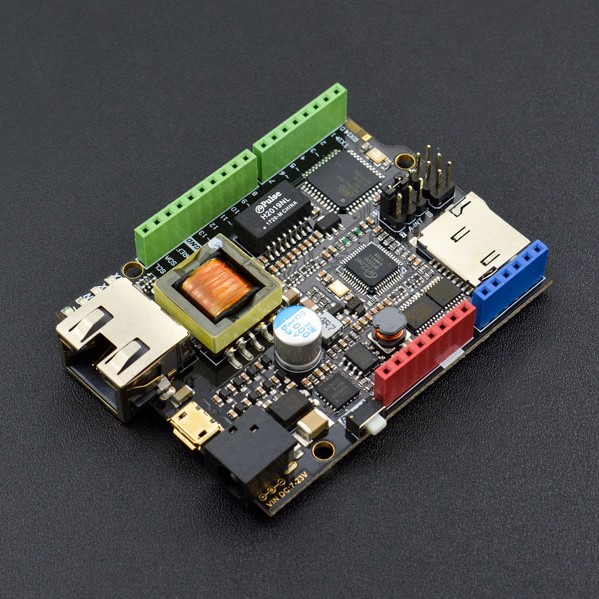
INTRODUCTION
W5500 chip is a Hardwired TCP/IP embedded Ethernet chip that provides easier Internet connection to embedded systems. It enables users to have the Internet connectivity in their applications just by using the board in which TCP/IP stack, 10/100 Ethernet MAC and PHY embedded. W5500 Ethernet Board is uses a high-efficiency SPI protocol, which supports 80 MHz speed for the high speed network communication. In order to reduce power consumption, it also provides WOL (Wake on LAN) and power down mode.
It has the same package size with Arduino Leonardo, and is compatible with most of Arduino shields and sensors. With a safer and more professional power regulation chip, the system can work under much more complex environments. And forget about power supply issues, since it work with POE power supply. Convenient huh?
Version Update: V2.0 has upgraded its POE power regulation circuit. which makes POE power more reliable.
SPECIFICATION
- Microcontroller: Atmel Atmega32u4 (Arduino Leonardo)
- External Input Voltage Plug (recommended): 7V~20V DC
- External Input Voltage Plug (limits): 6-23V
- POE Input Voltage: 48V AC/DC (802.3af standard PD device)
- Digital I/O Pins: 20
- Analog I/O Pins: 6
- DC Current per I/O Pin: 40 mA
- Flash Memory: 32 KB (ATmega32u4) of which 4KB used by bootloader
- SRAM: 2 KB (ATmega32u4)
- EEPROM: 1 KB (ATmega32u4)
- Clock Speed: 16 MHz
- PHY: WIZnet W5500
- PHY Clock Speed: 25MHz
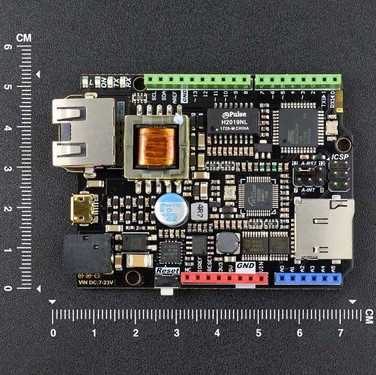
- Dimension: 73.5x53.5x15mm (2.89x2.11x0.59")
DOCUMENTS
SHIPPING LIST
- W5500 Ethernet with POE Mainboard x1
What is a W5500 chip?
The W5500 chip is a Hardwired TCP/IP embedded Ethernet controller that provides easier Internet connection to embedded systems. W5500 enables users to have the Internet connectivity in their applications just by using the single chip in which TCP/IP stack, 10/100 Ethernet MAC and PHY embedded.
WIZnet‘s Hardwired TCP/IP is the market-proven technology that supports TCP, UDP, IPv4, ICMP, ARP, IGMP, and PPPoE protocols. W5500 embeds the 32Kbyte internal memory buffer for the Ethernet packet processing. If you use W5500, you can implement the Ethernet application just by adding the simple socket program. It’s faster and easier way rather than using any other Embedded Ethernet solution. Users can use 8 independent hardware sockets simultaneously.
SPI (Serial Peripheral Interface) is provided for easy integration with the external MCU. The W5500’s SPI supports 80 MHz speed and new efficient SPI protocol for the high speed network communication. In order to reduce power consumption of the system, W5500 provides WOL (Wake on LAN) and power down mode.
Version Update: V2.0 has been upgraded a lot based on the old V1.0 (Click to check the Wiki). We mainly changed the original non-isolated power supply mode to isolated power supply to further improve the stability of the product.

 NOTE
NOTE
-
This board has a POE power supply unit whose voltage can reach up to 50V. Although it is not harmful for humman beings, please do not touch the circuit borad with your hands or other conductors since there are some low-voltage circuits on the board that cannot bear such high voltage. Otherwise, product damage may occur.
-
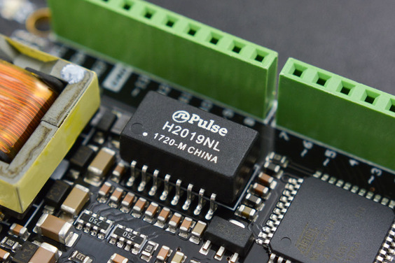
The transformer and power chip used by this mainboard will generate a lot of heat in high-load using, so please use the product in a good heat dissipation environment to avoid product damage or high temperature scald caused by overheating.
Application
- Home network equipment: set-top box, PVR, digital media center
- Serial Ethernet: access control system, LED display, wireless AP relay, etc
- Parallel Ethernet: POS or handheld printer, copier
- USB Ethernet: storage device, network printer
- Security system: webcam
- Monitoring equipment
- Embedded server
Specification
- Microcontroller: Atmel Atmega32u4 (Arduino Leonardo)
- External Input Voltage Range (recommended): 7V~23V DC
- External Input Voltage Range (limit): <24V DC
- POE Input Voltage: 48V AC/DC (802.3af standard compliant PD device)
- Digital I/O Pins: 20
- Analog I/O Pins: 6
- DC Current per I/O Pin: 40mA
- Flash Memory: 32KB (ATmega32u4) (4KB used by bootloader)
- SRAM: 2KB (ATmega32u4)
- EEPROM: 1KB (ATmega32u4)
- Clock Speed: 16MHz
- PHY: WIZnet W5500
- PHY Clock Speed: 25MHz
- Dimension: 73.5x53.5x15mm/2.89x2.11x0.59 inches
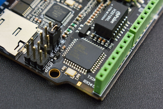
Pinout Diagram
We recommend that you remove the jumper caps if you don't need to use the W5500 reset and interrupt functions, or pins 7, 8, 11 or 12 may not function properly.
- L: D13 digital pin level indicator
- TX: serial data transmitting indicator
- RX: serial data receiving indicator
- ON: power indicator

Power Supply
-
POE: IEEE 802.3af standard PSE power supply
-
USB: micro USB
-
VIN power supply: external 7-23V power (Marked on PCB)
-
5V Pin: 5V power
Automatically select the highest voltage as power input.
Tutorial
Preparation
-
Standard POE Protocol Ethernet Swtich X1
-
W5500 Ethernet with POE Mainboard X1
-
Micro USB cable X1
-
RJ45 network cable X2
Step 1
Connect W5500 Reset pins: Connect A-RST pin to D11. (Default: Connected)

Step 2
Plug one end of the ethernet cable to W5500 mainboard, another end to any LAN ports of the Ethernet Switch, or you can use normal Internet switch or router device to directly connect to a PC's network interface (the module needs to be powered up here).

Step 3
Connect the W5500 mainbord to a computer with a USB cable.

Step 4
Download the WIZnet official Arduino library here. Unpack the downloaded file and then, place the Ethernet file under Arduino IDE 1.0.x or Arduino IDE 1.5.x in the libraries file of Arduino IDE according to your Arduino IDE version (overlap the original Ethernet library). Open Arduino IDE editor, find WebServer example in File->Example->Ethernet and open it.
-
Download the W5500 Ethernet library here
-
Replace the existing Ethernet library according to your Arduino IDE version:


NOTE: Good news! You can use arduino IDE v1.7 from Arduino.org that has "Ethernet 2" library, which works with this board. It means you don't have to download any modded libraries. Thank for the Vladimir Akopyan comments. Welcome to share your projects and comments on the Disqus.
Step 5: Pin Definitions
Note: These parts should be declared at the beginning of the sketch.
1. Define W5500 SPI “SS” pin and “Reset” Pin:
#define SS 10U //D10----- SS
#define RST 11U //D11----- Reset
2. Setup function
void setup() {
pinMode(SS, OUTPUT);
pinMode(RST, OUTPUT);
digitalWrite(SS, LOW);
digitalWrite(RST,HIGH); //Reset
delay(200);
digitalWrite(RST,LOW);
delay(200);
digitalWrite(RST,HIGH);
delay(200); //Wait W5500
Example
Open Arduino IDE, Select Boards -->Arduino Leonardo and COM port
Check that it works
Open the Arduino Serial Monitor to initialize the setup and you will see some information about the connection processing. Open your browser, input the IP address and you should get see data of 5 virtual analog pins:

NOTE: If you want to skip the serial monitor step, you can comment out the lines waiting for !serial, and add a line: delay(2000); to ensure that initialization has finished.
POE Power Supply
This board supports POE power supply, so it doesn’t need any other power source if you use an active ethernet connection. For more information please check: POE (Power Over Ethernet)Wikipedia
FAQ
|
Q&A |
Some general Arduino Problems/FAQ/Tips |
|---|---|
|
Q |
How to set the IP address? |
|
A |
Open your Network connection properties, and check the IPv4 Address and Gateway. The first three numbers should be set as same as on your board. The last number can be any number between 0-255, as long as it is not occupied by any other devices. |
|
Q |
About Old Version Library |
|
A |
The Ethernet library that comes along with Arduino IDE is for W5100 Ethernet shield, which is not compatible with W5500. Hence that you need to replace this library with the new one as instructed. |
|
Q |
About burning failure |
|
A |
This motherboard can only use version 1.0 and 1.5 of the Arduino IDE. If other versions of IDE are used, the compilation will fail. |
|
Q |
How to use the onboard micro-SD card slot? |
|
A |
Use it as the normal one using Arduino SD library is ok. Note that because the W5100 and SD card share the SPI bus, only one can be active at a time. For more, please check on Arduino, Arduino Ethernet Shield. |

More
- V1.0 Resource Download
- V2.0 Resource Download
วิธีการชำระเงิน
ชำระเงินค่าสินค้าโดยการโอนเงินเข้าบัญชีธนาคาร KBANK, SCB, BBL,TMB
กรุณาเก็บหลักฐานการโอนเงินของท่านไว้เพื่อแจ้งการชำระเงินด้วยค่ะ
ท่านสามารถแจ้งการชำระเงินผ่านระบบอัตโนมัติได้โดย Click Link ข้างล่างค่ะ
https://www.arduitronics.com/informpayment
ชำระเงินผ่านธนาคาร


@rfm0967y
ติดต่อสอบถาม
Join เป็นสมาชิกร้านค้า
MEMBER
