
Water-proof Ultrasonic Sensor (ULS) - แท้จาก DFRobot


| รหัสสินค้า | AS00313 |
| หมวดหมู่ | LIDAR / เซ็นเซอร์วัดระยะทาง / ความเร็ว Distance / Speed |
| ราคา | 1,285.00 บาท |
| สถานะสินค้า | พร้อมส่ง |
| จำนวน | ชิ้น |

รายละเอียดสินค้า
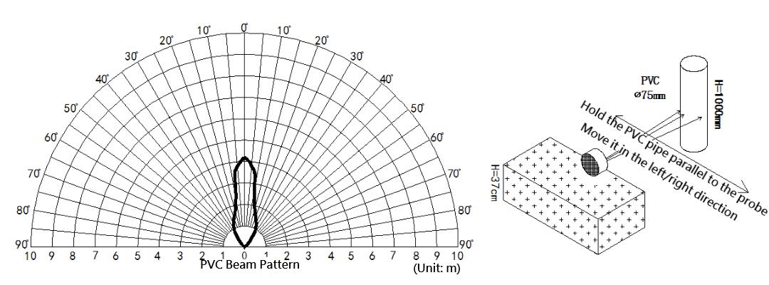
ULS Beam Directionalities Diagram
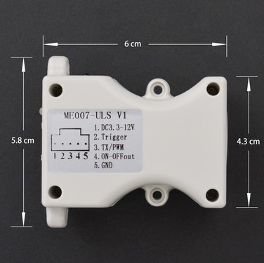
Dimension Diagram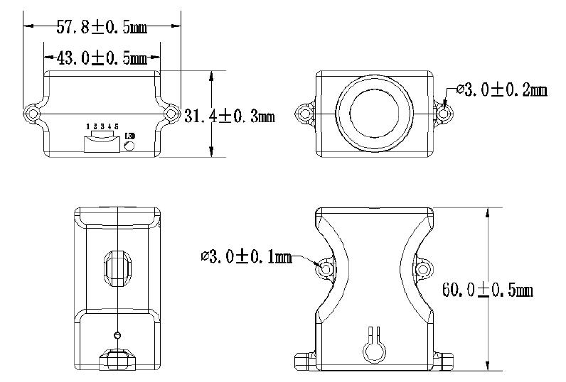
- High Degree of Protection
- Wide Power Supply Range, Low Power Consumption
- High Measuring Accuracy and Resolution
- High-Precision Temperature Output and Temperature Compensation Function
- Varied Output Modes: Serial Port, PWM, Switch
SPECIFICATION
- Supply Voltage: 3.3V~12V
- Operating Current: average current 5mA (based on power supply: 5V; duty cycle: 250ms)
- Center Frequency: 40KHz
- Blind Zone: 270mm
- Maximum Detection Distance: 8000mm
- Resolution: 1mm
- Operating Temperature: -15℃-60℃
- Storage Temperature: -25℃-80℃
- Product wiki
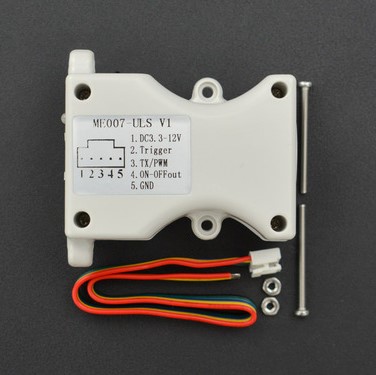
- Water-proof Ultrasonic Sensor (ULS) x1
- Screw bag x1
- Connector x1
Operation Instruction
The ultrasonic sensor has three output modes: serial, PWM, switch. The default output mode of the sensor is serial output. Change the mode by pressing or triggering. The indicators will flash in different ways to indicate the corresponding mode.
Button Operation Description
- Short-press (less than 2s): serial and PWM output modes can be switched in turn by short-pressing. When successfully switched, the module will remember the mode, and it won't be lost when powered down.
- Long-press (more than 3s): the controller will save the currently detected vaule and take it as threshold distance value under Switch mode. After the setting is done, the module will remember the threshold value and it won't lost when powered down.
Trigger Signal
- When the trigger pin "2.Trigger" is at High Level, the controller will be in standby state of low-power consumption.
- When the trigger pin "2. Tigger" is at falling edge, the Low Level of the falling edge should keep 0.1~10ms. (1) Under UART output mode, the controller will be triggerred once and then output one frame serial data;(2) Under PWM output mode, the controller will be triggerred one and output PWM signal.
- When the trigger pin "2.Trigger" is at Low Level or be grounded, the controller will be under Switch Mode.
Indicator Description
- When successfully switched to PWM mode by short-pressing, the LED will flash blue once, wait 1 second, and flash once again.
- When successfully switched to serial mode by short-pressing, the LED will flash blue three times, wait 1 second, and flash three times again.
- When the threshold value is set successfully by long-pressing, the LED will flash red and blue five times alternately.
- When the controller is in the Serial or PWM mode, it will be triggered once by the falling edge, and the LED will flash red once.
- When the controller is in the Switch mode, the LED will indicate the state of the Switch. If the currently detected value is within the range of the thresholds value, the LED will emit red. if not, the LED turns off.
Output Format

| Num | Pin | Description |
|---|---|---|
| 1 | VCC | 3.3V~12V Power input |
| 2 | Trigger | Trigger |
| 3 | TX/PWM | Serial and PWM Output |
| 4 | ON-OFFout | Switch Output |
| 5 | GND | Ground |
Serial Output
The default output mode of the product is serial mode. If currently it is not in the serial mode, you can switch to this mode by short-pressing. when successfully switched, the LED flashes blue three times, stop 1 second and flashes three times again.
When the trigger pin "2.Trigger" is at falling edge and the Low level is kept for 0.1-10ms, the controller will be triggerred once, and the output pin "3.TX/PWM" will output one frame serial data of 3.3V TTL with temperature compensation. The trigger period of the controller must be over 60ms.

Note: T1=0.1-10ms; T2=4-6ms; T3=1-55ms
Command frame format of serial communication
| Interface Type | Start byte | Data byte | Stop byte | Parity check | Band rate |
|---|---|---|---|---|---|
| Full duplex | 1 | 8 | 1 | None | 9600 |
Output frame format
| Frame Header ID | Distance Data High | Distance Data Low | Temperature Data High | Temperature Data Low | Checksum |
|---|---|---|---|---|---|
| 0xFF | Data_H | Data_L | Temp_H | Temp_L | SUM |
Distance Calculation
Distance=Data_H*256+Data_L (Unit: mm)
Temperature Calculation
When the highest bit of Temp_H is 0, the temperature value is positive; when it is 1, the temperature value is negative.
If Temp_H=0x01=0b0000 0001, the most highest bit is 0, which means the temperature value is positive.
Temperature=Temp _H*256+ Temp _L
Eg: the temperature value is 281 when converted to decimal; The currently detected temperature is 28.1℃. (Unit: ℃)
Checksum Calculation
Note: just reserve the eight lower bits of the accumulated value of checksum.
SUM=(frame header+ Data_H+ Data_L+ Temp_H+ Temp_L)&0x00FF
PWM Output
Switch to PWM mode by short-pressing the button. When succeeded, the LED flashes blue once, wait 1 second, then flash once again.
When the trigger pin "2.Trigger" is at falling edge and the Low level is kept for 0.1-10ms, the controller will be triggerred once and the output pin "3.TX/PWM" will output PWM signal of 3.3V TTL. The trigger period of the controller must be over 60ms.
Output Principle
When the trigger pin received the falling edge trigger level, the module will emit 40kHz ultrasound, at the same time, the output pin "3.TX/PWM" will be pulled up. when it detected the echo signal, the output pin will be pulled down immediately. When it did't detect any objects, the output pin will be pulled down to stop detecting after 55ms, and there is no temperature compensation in this process.
Use MCU to judge the time of high level, which also is the time for the ultrasound to travel between the module and the detected object. The distance can be calculated then when we get the ultrasound velocity and the time.

Note: T1=0.1-10ms; T2=4-6ms; T3=1-55ms
Calculation
Distance=High level time×Velocity(340m/s)/2, us/58=cm or us/148=inch; in different temeprature, the velocity of the ultrasound: v=332+0.6t(m/s). If the controller did't detect any objects, the output pin will output constant pulse width for 55ms.
Switch Output
When the trigger pin "2.Trigger" is at low level or grounded, the controller will be in Switch mode, and automatically starts detecting with 250ms working period. Compare the detected value with the pre-set threshold value so as to control the output state of the switch.
Set the threshold value
Step 1: evaluate the threshold distance value, put an object or baffle at the distance equal to the preset threshold distance. For instance, when we set the threshold vlaue to 3m, then we need to place a flat baffle at 3m away. Level the baffle on the ground to form an open field so as to assure the detection accuracy.
Step 2: direct the controller at the object or the flat baffle, long-press for 3 seconds above. When the LED flashed red and blue alternately, the setting is done. The controller will remember the currently detected distance and take it as the threshold value. Continue to long-press the button if you need to reset the threshold value.
Output State
Case 1: if the detected value is smaller than the preset threshold, the output pin "4.ON-OFFout" output low value, at the same time, the LED emits red.
Case 2: if the detected vaule is bigger than the perset threshold, "4.ON-OFFout" output pull-up high level and the LED turns off.
ULS Tutorial
Requirements
-
Hardware
- Arduino UNO R3 (or similar) x 1
- Water-proof Ultrasonic Sensor (ULS) x1
- Connectors
-
Software
Connection Diagram

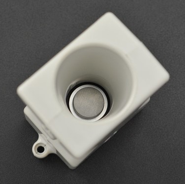
 Note: the internal probe surface is regarded as the detecting starting point by default. If you take the plane of the bell-mouth as starting point, then the distance will be the detected distance minus 40mm.
Read serial port data
* ****************************************************
* @brief Water-proof Ultrasonic Sensor (ULS)

* @copyright [DFRobot](http://www.dfrobot.com), 2016
* @copyright GNU Lesser General Public License

* @author [Xiaoyu](Xiaoyu.zhang@dfrobot.com)
* @version V1.0
* @date 2019-03-11

* GNU Lesser General Public License.
* All above must be included in any redistribution
* ****************************************************/
#include
SoftwareSerial mySerial(10, 11); // RX, TX
char col;
unsigned char buffer_RTT[6] = {};
int Rage = 0;
float Temp = 0;
int Tflag = 0;
void setup() {
Serial.begin(57600); // Enable the serial port and set the band rate to 57600 bps
mySerial.begin(9600);
pinMode(LED_BUILTIN, OUTPUT);
digitalWrite(LED_BUILTIN, HIGH);
}
void loop() {
digitalWrite(LED_BUILTIN, HIGH);
delay(100);
digitalWrite(LED_BUILTIN, LOW);
delay(4);
digitalWrite(LED_BUILTIN, HIGH);
do{
for (int j = 0; j <= 5; j++){
col = mySerial.read();
buffer_RTT[j] = (char)col;
}
} while(mySerial.read() == 0xff);
mySerial.flush();
if(buffer_RTT[0]==0xff){
int cor;
cor=(buffer_RTT[0]+buffer_RTT[1]+buffer_RTT[2]+buffer_RTT[3]+buffer_RTT[4])&0x00FF;//Check
if(buffer_RTT[5]==cor)
{
Rage = (buffer_RTT[1] << 8) + buffer_RTT[2];
Tflag= buffer_RTT[3]&0x80;
if(Tflag==0x80){
buffer_RTT[3]=buffer_RTT[3]^0x80;
}
Temp = (buffer_RTT[3] << 8) + buffer_RTT[4];
Temp = Temp/10;
}
else{
Rage = 0;
Temp = 0;
}
}
Serial.print("Rage : ");
Serial.print(Rage);//Output distance unit mm
Serial.println("mm");
Serial.print("Temperature: ");
if(Tflag ==0x80)
{
Serial.print("-");
}
Serial.print(Temp);//Output temperature
Serial.println("℃");
Serial.println("============================== ");
} 
PWM Output
* ****************************************************
* @brief Water-proof Ultrasonic Sensor (ULS)

* @copyright [DFRobot](http://www.dfrobot.com), 2016
* @copyright GNU Lesser General Public License

* @author [Xiaoyu](Xiaoyu.zhang@dfrobot.com)
* @version V1.0
* @date 2019-03-11

* GNU Lesser General Public License.
* All above must be included in any redistribution
* ****************************************************/
#include
char col;// for storing the data read from the serial port
unsigned long duration;
int datapin = 10;
int val = 0;
void setup() {
Serial.begin(57600); //Enable the serial port and set band rate to 57600 bps
pinMode(LED_BUILTIN, OUTPUT);
pinMode(datapin, INPUT);
digitalWrite(LED_BUILTIN, HIGH);
}

void loop(){
digitalWrite(LED_BUILTIN, HIGH);
delay(57);
digitalWrite(LED_BUILTIN, LOW);
delay(4); //give level signal
duration = pulseIn(datapin, HIGH);//read the high level pulse on the pin, the maximum pulse interval is 55ms; assign the result to the variable "duration"
delay(3);
digitalWrite(LED_BUILTIN, HIGH);//Pull up the signal pin
duration = duration/ 58.00; //convert time to distance
Serial.print(duration);//serial port print data
Serial.println("cm");
Serial.println("=========== ");
} 
Switch Output
* ****************************************************
* @brief Water-proof Ultrasonic Sensor (ULS)

* @copyright [DFRobot](http://www.dfrobot.com), 2016
* @copyright GNU Lesser General Public License

* @author [Xiaoyu](Xiaoyu.zhang@dfrobot.com)
* @version V1.0
* @date 2019-03-11

* GNU Lesser General Public License.
* All above must be included in any redistribution
* ****************************************************/
#include
SoftwareSerial mySerial(10, 11); // RX, TX
unsigned char buffer_RTT[7] = {};
unsigned long duration;
int datapin = 9;
void setup() {
Serial.begin(57600); // Enable serial port and set band rate to 57600 bps
mySerial.begin(9600);
pinMode(LED_BUILTIN, OUTPUT);
pinMode(datapin, INPUT);
digitalWrite(LED_BUILTIN, HIGH);
}

void loop() {
digitalWrite(LED_BUILTIN, LOW);//give low level
duration = digitalRead(datapin);//read pin state
delay(3);
switch(duration){
case 0 :Serial.println("LOW"); break;//the distance to the object is less than the preset distance, set the defalut to 1m
case 1 :Serial.println("HIGH"); break;//the distance to the object is more than the preset distance
}
} 
วิธีการชำระเงิน
ชำระเงินค่าสินค้าโดยการโอนเงินเข้าบัญชีธนาคาร KBANK, SCB, BBL,TMB
กรุณาเก็บหลักฐานการโอนเงินของท่านไว้เพื่อแจ้งการชำระเงินด้วยค่ะ
ท่านสามารถแจ้งการชำระเงินผ่านระบบอัตโนมัติได้โดย Click Link ข้างล่างค่ะ
https://www.arduitronics.com/informpayment
ชำระเงินผ่านธนาคาร


@rfm0967y
ติดต่อสอบถาม
Join เป็นสมาชิกร้านค้า
MEMBER
