Description:
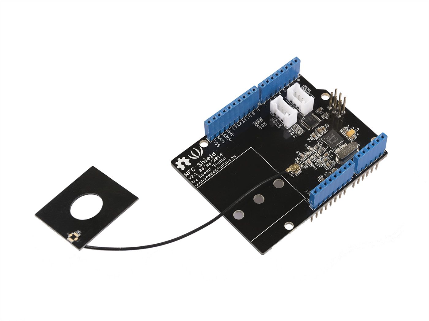
Short for Near Field Communication, NFC is a widely used technology around us. It's behind daily applications such as access control system and mobile payment system. NFC Shield features a highly integrated transceiver module PN532 which handles contactless communication at 13.56MHz. You can read and write a 13.56MHz tag with this shield or implement point to point data exchange with two NFC Shields.
In this new version, we assign an independent PCB antenna which can easily stretch out of any enclosure you use, leaving more room for you to design the exterior of your project.
The PCB comes stuck on the shield, but you can easily peel it off.
Features
-
5cm max effective range
-
SPI pin saving interface
-
Serve for contactless communication at 13.56MHz
-
Support P2P communication
-
Support ISO14443 Type A and Type B protocals
Technical details
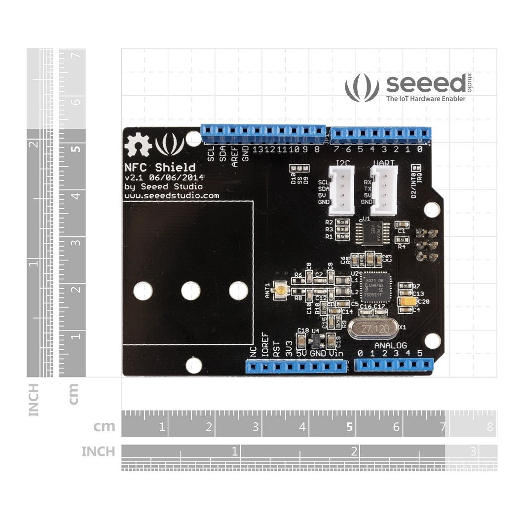
| Dimensions |
100mm x65mm x30mm |
| Weight |
G.W 39g |
Hardware Overview
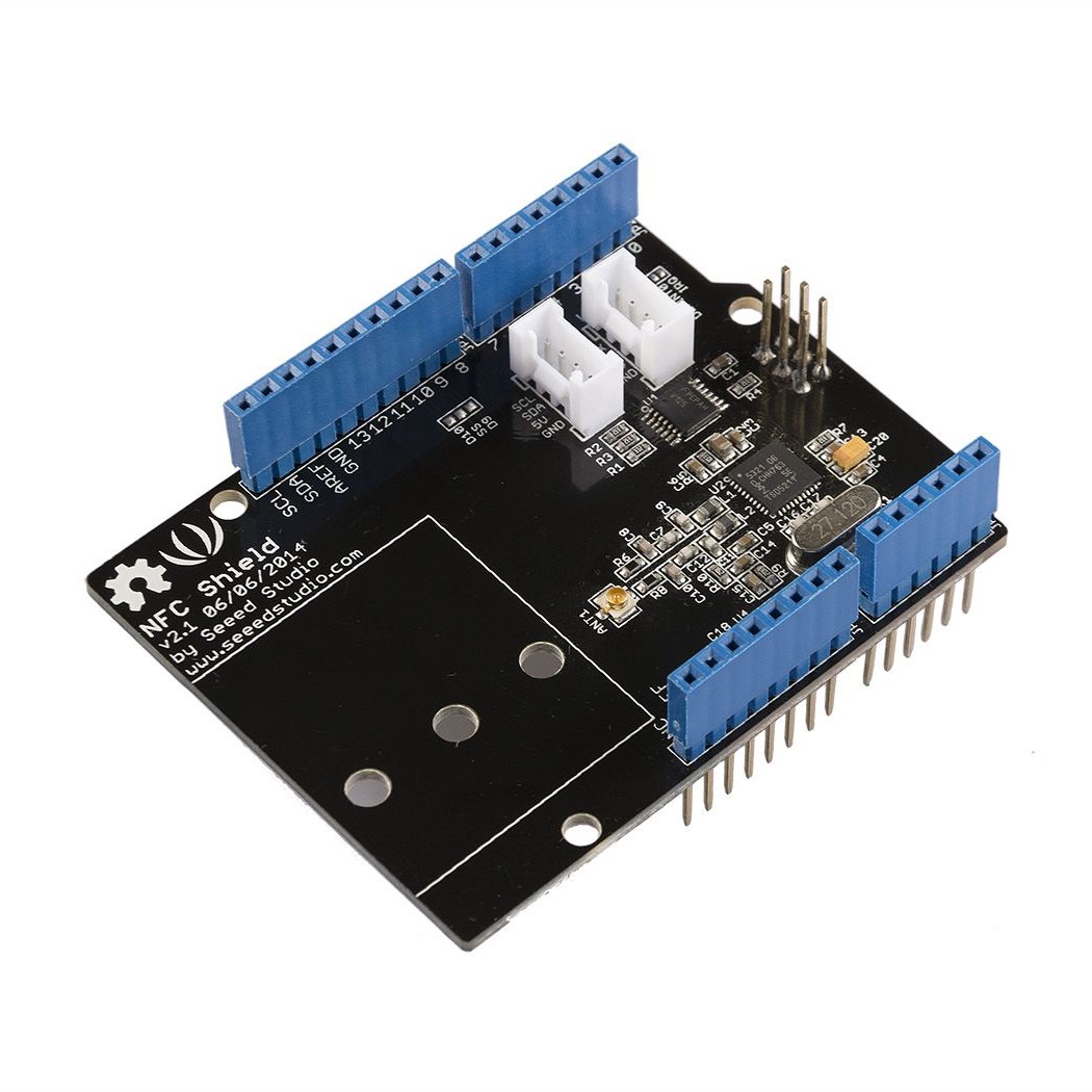
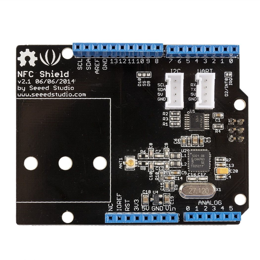
The NFC shield's pins and other terminals are described below.
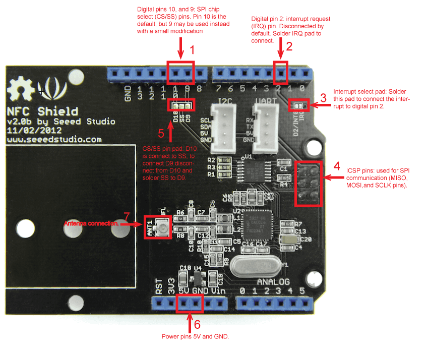
NFC shield interface
- D10 and D9 are used for SPI chip select (CS/SS). D10 is connected by default, to connect D9 soldering the SS pad to the D9 pad and scraping off the connection between SS and D10 is required.
- D2 can be used to receive the shield's interrupt request (IRQ) pin signal. The interrupt is not connect by default, soldering of the "D2/INT0" and "IRQ" pads is required.
- The shield gets its SPI interface (SPI MOSI, MISO, and SCK pins) from the Arduino's ICSP header directly, this means that the shield works the following Arduinos: Uno, Mega, and Leonardo.
- The ANT1 terminal is where the NFC antenna (included with the shield) is connected to.
- The shield is powered by 5V from the Arduino board.
The NFC shield's antenna, included with the shield, is a separate PCB module that is attached to the shield via a cable. The antenna is the area used to receive and transmit information.
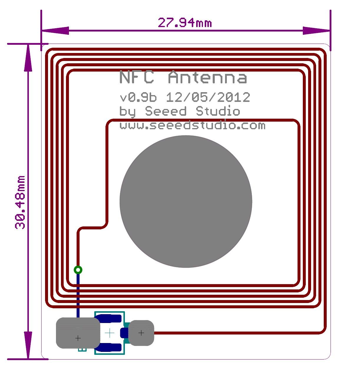
NFC antenna PCB attachment
NFC Shield Setup
Hardware Installation
- Attach the NFC Antenna to the shield.
- Stack the NFC Shield on your Arduino development board and connect the board to a PC using a USB cable.
Software Libraries Installation
- Close the Arduino IDE if you have it open.
- Download the PN532 library ZIP folder and extract the files.
- Copy the folders PN532, PN532_HSU, PN532_SPI, and PN532_I2C into the Arduino "libraries" folder.
- Download Don's NDEF library ZIP folder and extract the files.
- Open the extracted folder and rename the "NDEF-master" folder to "NDEF".
- Copy the "NDEF" folder to the Arduino "libraries" folder.
- Restart the Arduino IDE. You should now be able to see "NDEF" and "PN532" as options in the Arduino "Examples" sub-menu (See figure below).
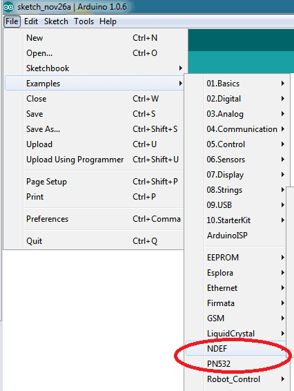
Arduino available libraries menu
NFC Shield Examples/Applications
Example #1: NFC Tag Scan
This example will show you how to use the NFC shield to scan an NFC tag and display its information/data.
In the Arduino IDE copy, paste, then upload the code below to your board.
Code
 1
2
3
4
5
6
7
8
9
10
11
12
13
14
15
16
17
18
19
20
21
22
23
24
|
 #include
#include "PN532_SPI.h"
#include "PN532.h"
#include "NfcAdapter.h"

PN532_SPI interface(SPI, 10); // create a PN532 SPI interface with the SPI CS terminal located at digital pin 10
NfcAdapter nfc = NfcAdapter(interface); // create an NFC adapter object

void setup(void) {
Serial.begin(115200); // begin serial communication
Serial.println("NDEF Reader");
nfc.begin(); // begin NFC communication
}

void loop(void) {

Serial.println("\nScan an NFC tag\n");
if (nfc.tagPresent()) // Do an NFC scan to see if an NFC tag is present
{
NfcTag tag = nfc.read(); // read the NFC tag into an object, nfc.read() returns an NfcTag object.
tag.print(); // prints the NFC tags type, UID, and NDEF message (if available)
}
delay(500); // wait half a second (500ms) before scanning again (you may increment or decrement the wait time)
}
|
To test the code:
- Open the Arduino Serial monitor window
- Set the baudrate to 115200
- Hold an NFC tag over the NFC antenna area
- The NFC shield will scan the tag and you should be able to see the NFC tag’s UID, tag type, and message (if available) in the serial monitor window. See the figure below.
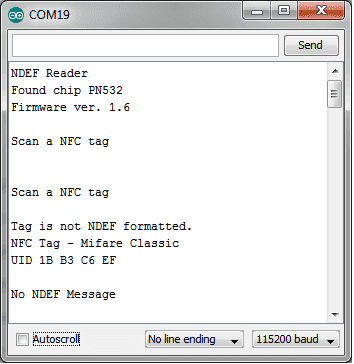
Example #1 serial communication window output when scanning an NFC tag.
Example #2: NFC(keyless) Door Lock
This example will show you how to use an NFC tag as a key to unlock a door or a lock. The door/lock mechanism will be left to your imagination, we'll only cover the NFC part of the code.
- Do Example #1: NFC Tag Scan, above, to get your NFC tag's UID.
- Optional Step - connect a green LED to pin 3 as shown in the figure/schematic below. We'll use this LED to signal a successful match in keys.
-
Optional Step – connect a red LED to pin 4 as shown in the figure/schematic below. We'll use this LED to signal a mismatched key.
-
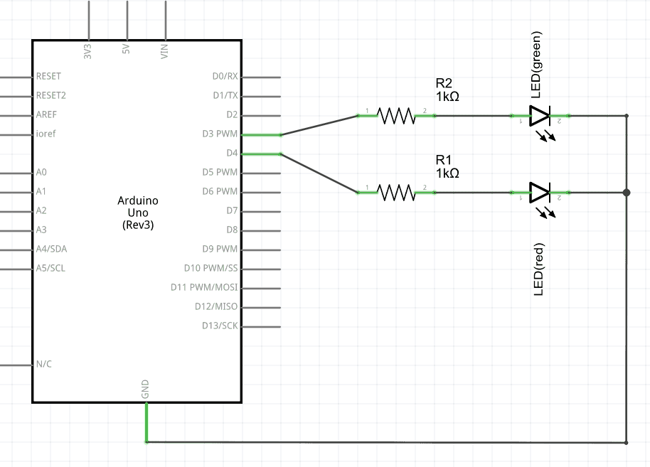
NFC lock circuit
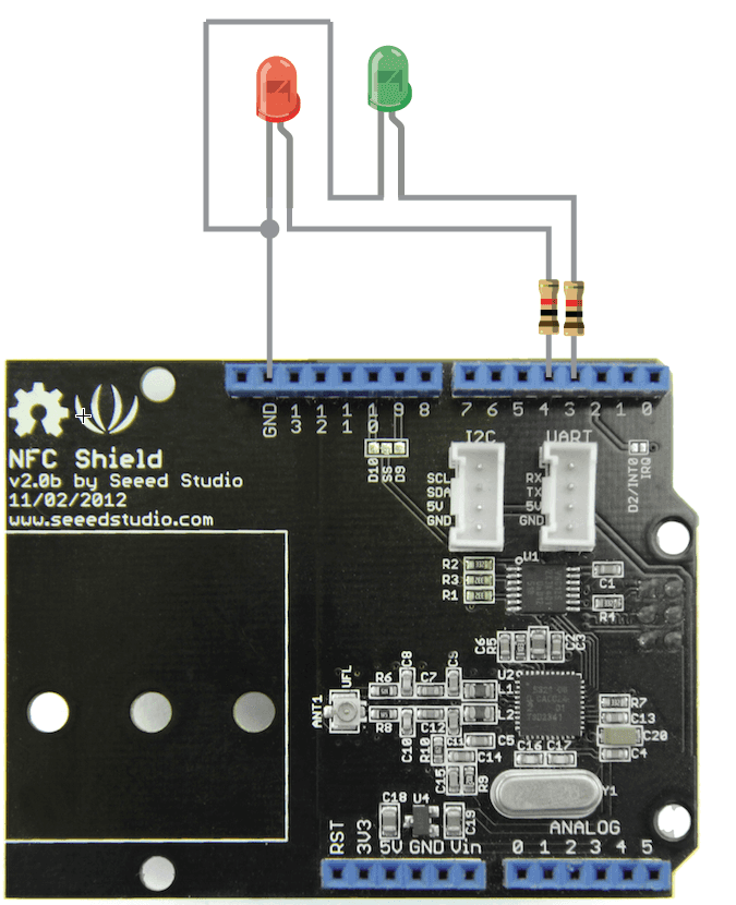
NFC lock circuit
-
In the Arduino IDE create a new sketch and copy, paste, and upload the code below to your Arduino board replacing the myUID string constant with your tag’s UID obtained from Example #1.
Code
 1
2
3
4
5
6
7
8
9
10
11
12
13
14
15
16
17
18
19
20
21
22
23
24
25
26
27
28
29
30
31
32
33
34
35
36
37
38
39
40
41
42
43
44
45
46
47
48
49
50
51
52
53
54
55
56
57
58
59
60
61
62
63
64
65
66
67
68
|
 #include
#include "PN532_SPI.h"
#include "PN532.h"
#include "NfcAdapter.h"

String const myUID = "1B B3 C6 EF"; // replace this UID with your NFC tag's UID
int const greenLedPin = 3; // green led used for correct key notification
int const redLedPin = 4; // red led used for incorrect key notification

PN532_SPI interface(SPI, 10); // create a SPI interface for the shield with the SPI CS terminal at digital pin 10
NfcAdapter nfc = NfcAdapter(interface); // create an NFC adapter object

void setup(void) {
Serial.begin(115200); // start serial comm
Serial.println("NDEF Reader");
nfc.begin(); // begin NFC comm

// make LED pins outputs
pinMode(greenLedPin,OUTPUT);
pinMode(redLedPin,OUTPUT);

// turn off the LEDs
digitalWrite(greenLedPin,LOW);
digitalWrite(redLedPin,LOW);
}

void loop(void) {

Serial.println("Scanning...");
if (nfc.tagPresent()) // check if an NFC tag is present on the antenna area
{
NfcTag tag = nfc.read(); // read the NFC tag
String scannedUID = tag.getUidString(); // get the NFC tag's UID

if( myUID.compareTo(scannedUID) == 0) // compare the NFC tag's UID with the correct tag's UID (a match exists when compareTo returns 0)
{
// The correct NFC tag was used
Serial.println("Correct Key");
// Blink the green LED and make sure the RED led is off
digitalWrite(greenLedPin,HIGH);
digitalWrite(redLedPin,LOW);

delay(500);
digitalWrite(greenLedPin,LOW);
delay(500);
digitalWrite(greenLedPin,HIGH);
delay(500);
digitalWrite(greenLedPin,LOW);
// put your here to trigger the unlocking mechanism (e.g. motor, transducer)
}else{
// an incorrect NFC tag was used
Serial.println("Incorrect key");
// blink the red LED and make sure the green LED is off
digitalWrite(greenLedPin,LOW);
digitalWrite(redLedPin,HIGH);

delay(500);
digitalWrite(redLedPin,LOW);
delay(500);
digitalWrite(redLedPin,HIGH);
delay(500);
digitalWrite(redLedPin,LOW);
// DO NOT UNLOCK! an incorrect NFC tag was used.
// put your code here to trigger an alarm (e.g. buzzard, speaker) or do something else
}
}
delay(2000);
}
|
To test the code/application:
- Open the Arduino's serial monitor window
- Hold the NFC tag with the correct key on the antenna area.
- The green LED should light up and the serial window should print "Correct Key"
- Now hold a different NFC on the antenna area
- The red LED should light up and the serial window should print "Incorrect Key"
Example #3: How to use the Interrupt Pin (Example #2: Revisited)
Although the code in Example #2 above does what we need there is a more elegant approach to handling NFC tag detections. In this example we'll show you how to make use of the interrupt pin in the NFC shield so that instead of polling the shield (asking "is there a tag present?") we wait for the shield to tell the Arduino that a tag is available to be read. Why would you want to do this? There are many reasons and interrupts are a whole different topic, but one reason that may convince you is that your project/circuit will save battery since we are not triggering the shield circuit continuously.
Hardware Modification
The NFC shield’s interrupt pin (IRQ) is disconnect from the Arduino's digital pin 2 (D2), to connect the IRQ and D2 pin together go ahead and solder the pad on the shield labeled "D2/INT0 IRQ".
Code
Upload the following code to your Arduino board:
 1
2
3
4
5
6
7
8
9
10
11
12
13
14
15
16
17
18
19
20
21
22
23
24
25
26
27
28
29
30
31
32
33
34
35
36
37
38
39
40
41
42
43
44
45
46
47
48
49
50
51
52
53
54
55
56
57
58
59
60
61
62
63
64
65
66
67
68
69
70
71
72
73
74
75
76
77
78
79
80
81
82
83
84
85
86
87
88
89
90
91
92
93
94
95
96
97
98
99
100
101
102
103
104
105
106
107
108
109
110
111
112
113
114
115
116
117
118
119
120
121
122
123
124
125
126
127
128
129
130
131
132
133
134
135
136
137
138
139
140
141
142
143
144
145
146
147
148
149
150
|
 #include
#include "PN532_SPI.h"
#include "PN532.h"
#include "NfcAdapter.h"

// FLAG_NONE used to signal nothing needs to be done
#define FLAG_NONE 0
// FLAG_IRQ_TRIGGERED used to signal an interrupt trigger
#define FLAG_IRQ_TRIGGERED 1
// FLAG_RESET_IRQ used to signal that the interrupt needs to be reset
#define FLAG_RESET_IRQ 2
// flags variable used to store the present flag
volatile int flags = FLAG_NONE;

String const myUID = "1B B3 C6 EF"; // replace this UID with your NFC tag's UID
// LED pins
int const greenLedPin = 3; // green led used for correct key notification
int const redLedPin = 4; // red led used for incorrect key notification

// the interrupt we'll be using (interrupt 0) is located at digital pin 2
int const irqPin = 2; // interrupt pin

PN532_SPI interface(SPI, 10); // create a SPI interface for the shield with the SPI CS terminal at digital pin 10

NfcAdapter nfc = NfcAdapter(interface); // create an NFC adapter object

String scannedUID = ""; // this is where we'll store the scanned tag's UID

void setup(void) {
// make LED pins outputs
pinMode(greenLedPin,OUTPUT);
pinMode(redLedPin,OUTPUT);

Serial.begin(115200); // start serial comm
Serial.println("NDEF Reader");
nfc.begin(); // begin NFC comm

// turn off the LEDs
digitalWrite(greenLedPin,LOW);
digitalWrite(redLedPin,LOW);
// attach the function "irq" to interrupt 0 on the falling edges
attachInterrupt(0,irq,FALLING);// digital pin 2 is interrupt 0, we'll call the irq function (below) on the falling edge of this pin
}

void loop(void) {
int flag = getFlag(); // get the present flag

switch(flag) // check which flag/signal we are on
{
case FLAG_NONE:
// nothing needs to be done
break;
case FLAG_IRQ_TRIGGERED: // the interrupt pin has been triggered
Serial.println("Interrupt Triggered");
if (nfc.tagPresent())
{
// an NFC tag is present
NfcTag tag = nfc.read(); // read the NFC tag
scannedUID = tag.getUidString(); // get the NFC tag's UID
if(myUID.compareTo(scannedUID) == 0) // compare the NFC tag's UID with the correct tag's UID (a match exists when compareTo returns 0)
{
// the scanned NFC tag matches the saved myUID value
Serial.println("Correct tag/key");
blinkLed(greenLedPin,200,4); // blink the green led
// put your here to trigger the unlocking mechanism (e.g. motor, transducer)
}else{
// the scanned NFC tag's UDI does not match the myUID value
Serial.println("Incorrect tag/key");
blinkLed(redLedPin,200,4); // blink the red led
// DO NOT UNLOCK! an incorrect NFC tag was used.
// put your code here to trigger an alarm (e.g. buzzard, speaker) or do something else
}
// return to the original state
setFlag(FLAG_NONE);
reset_PN532_IRQ_pin();
}else{
// a tag was not present (the IRQ was triggered by some other action)
setFlag(FLAG_NONE);
}
break;
default:
// do any other stuff for flags not handled above
break;
}
}

/*
 * Name: setFlat
 * Description: used to set actions/flags to be executed in the loop(void) function
 * Parameters:
 * int flag - the action/flag to store
 * Returns: void
 */
void setFlag(int flag)
{
flags = flag;
}

/*
 * Name: getFlag
 * Description: used to get the present flag/action
 * Parameters: void
 * Returns: int - the flags variable. The action/flag set by setFlag
 */
int getFlag()
{
return flags;
}

/*
 * Name: irq
 * Description: Interrupt service routine (ISR). This function will be executed whenever there is a falling edge on digital pin 2 (the interrupt 0 pin)
 * Parameters: void
 * Returns: void
 */
void irq()
{
if(getFlag()==FLAG_NONE){
setFlag(FLAG_IRQ_TRIGGERED);
}
}
/*
 * Name: reset_PN532_IRQ_pin
 * Description: used to reset the PN532 interrupt request (IRQ) pin
 * Parameters: void
 * Returns: void
 */
void reset_PN532_IRQ_pin()
{
nfc.tagPresent();
}

/*
 * Name: blinkLed
 * Description: used to toggle a pin to blink an LED attached to the pin
 * Parameters:
 * ledPin - the pin where the led is connected to
 * delayTime - the time in milliseconds between HIGH and LOW
 * times - the number of times to toggle the pin
 * Returns: void
 */
void blinkLed(int ledPin,int delayTime,int times)
{
for(int i=0;i<times;i++){
digitalWrite(ledPin,HIGH);
delay(delayTime);
digitalWrite(ledPin,LOW);
delay(delayTime);
}
}
|
To test the code/application:
- If desired, connect the LEDs as shown in Example #2 above.
- Open the Arduino's serial monitor window
- Hold the NFC tag with the correct key on the antenna area.
- The green LED should light up and the serial window should print "Correct Key"
- Now hold a different NFC on the antenna area
- The red LED should light up and the serial window should print "Incorrect Key"
The serial window from our test of this code is displayed below, yours should be similar.
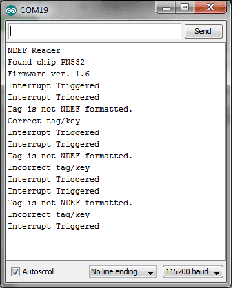
Serial comm window output from example 3.
Example #4: Write an NDEF Message to a Tag
NFC tags are capable of storing data, the amount of data is dependent on each tag. In this example we will store two strings/messages on a tag, you will then be able to read this message with the code in Example #6: Read an NDEF Message From a Tag.
Upload the following code to your Arduino development board.
Note
If your NFC tag is not properly formatted ("Message write failed" will be displayed in the serial comm window) you'll need to see if you tag can be formatted with the code in
Example #5: Format a Tag as NDEF
Code
 1
2
3
4
5
6
7
8
9
10
11
12
13
14
15
16
17
18
19
20
21
22
23
24
25
26
27
28
29
30
31
32
33
34
35
36
|
 #include
#include "PN532_SPI.h"
#include "PN532.h"
#include "NfcAdapter.h"

PN532_SPI interface(SPI, 10); // create a SPI interface for the shield with the SPI CS terminal at digital pin 10

NfcAdapter nfc = NfcAdapter(interface); // create an NFC adapter object

void setup(void)
{
Serial.begin(115200); // start serial comm
Serial.println("NDEF Reader");
nfc.begin(); // begin NFC comm
}

void loop(void)
{
Serial.println("Place a formatted Mifare Classic NFC tag on the reader.");
if(nfc.tagPresent())
{
NdefMessage message = NdefMessage();
message.addUriRecord("Hello, world!");
message.addUriRecord("How are you today?");

bool success = nfc.write(message);
if(success)
{
Serial.println("The message was successfully written to the tag.");Ho
}else{
Serial.println("Message write failed.");
}
}

delay(5000);
}
|
To test the code above:
- Open an Arduino serial comm window
- Hold the NFC tag over the NFC shield antenna's area and wait for the success or failure message to appear as shown in the figure below.
- Remove the NFC tag form the antenna's area as soon as the success message is displayed to prevent a rewrite.
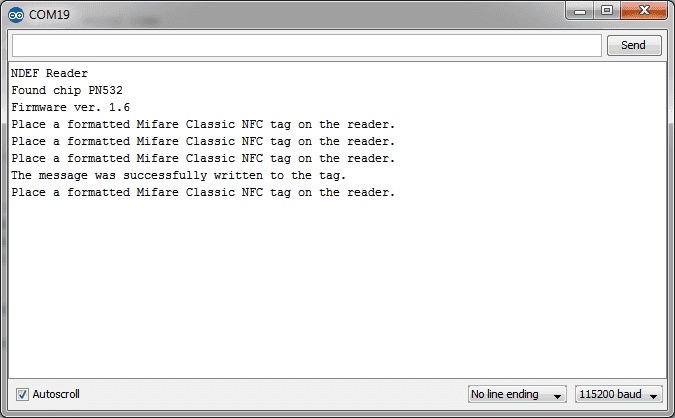
Serial comm window for NDEF message written to card example.
Your brand new NFC tag might not be NDEF formatted initially. To format a tag as NDEF upload the following code to your Arduino development board:
Code
 1
2
3
4
5
6
7
8
9
10
11
12
13
14
15
16
17
18
19
20
21
22
23
24
25
26
27
28
29
30
31
|
 #include
#include "PN532_SPI.h"
#include "PN532.h"
#include "NfcAdapter.h"

PN532_SPI interface(SPI, 10); // create a SPI interface for the shield with the SPI CS terminal at digital pin 10

NfcAdapter nfc = NfcAdapter(interface); // create an NFC adapter object

void setup(void)
{
Serial.begin(115200); // start serial comm
Serial.println("NDEF Reader");
nfc.begin(); // begin NFC comm
}

void loop(void)
{
Serial.println("Place an unformatted Mifare Classic tag on the reader.");
if (nfc.tagPresent()) {

bool success = nfc.format();
if (success) {
Serial.println("Success, tag formatted as NDEF.");
} else {
Serial.println("Format failed.");
}

}
delay(5000);
}
|
To test/run the code:
- Open the Arduino serial comm window.
- Hold the NFC tag you wish to format over the NFC shield antenna's area.
- Wait for the success or fail message to appear as shown in the figure below.
- Remove the NFC tag from the antenna's area to prevent a re-format.
Note
If your tag failed to get formatted, try again. If it fails your tag is not capable of getting formatted as NDEF.
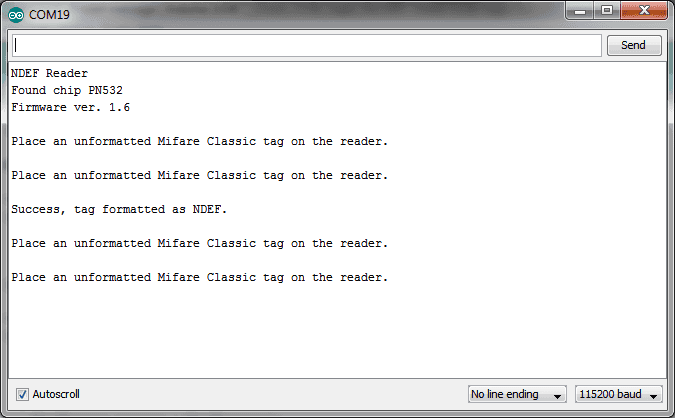
Serial comm window output when formatting an NFC tag to NDEF.
Example #6: Read an NDEF Message From a Tag
As you have seen in the example's above, the NFC shield is capable of writing messages to NFC tags. The NFC is also capable of reading NDEF messages from tags, in this example we'll show you how.
Code
Upload the following code to your Arduino development board.
 1
2
3
4
5
6
7
8
9
10
11
12
13
14
15
16
17
18
19
20
21
22
23
24
25
26
27
28
29
30
31
32
33
34
35
36
37
|
 #include
#include "PN532_SPI.h"
#include "PN532.h"
#include "NfcAdapter.h"

PN532_SPI interface(SPI, 10); // create a SPI interface for the shield with the SPI CS terminal at digital pin 10

NfcAdapter nfc = NfcAdapter(interface); // create an NFC adapter object

void setup(void)
{
Serial.begin(115200); // start serial comm
Serial.println("NDEF Reader");
nfc.begin(); // begin NFC comm
}

void loop(void)
{
Serial.println("\nScan an NFC tag\n");
if (nfc.tagPresent()) // Do an NFC scan to see if an NFC tag is present
{
NfcTag tag = nfc.read(); // read the NFC tag
if(tag.hasNdefMessage())
{
NdefMessage message = tag.getNdefMessage();
for(int i=0;i<message.getRecordCount();i++)
{
NdefRecord record = message.getRecord(i);
int payloadLength = record.getPayloadLength();
byte payload[payloadLength];
record.getPayload(payload);
Serial.write(payload,payloadLength);
}
}
}
delay(500); // wait half a second (500ms) before scanning again (you may increment or decrement the wait time)
}
|
To test code above:
- Open an Arduino serial comm window
- Hold the an NFC tag with an NDEF message over the NFC shield antenna's area.
- The NDEF message written on the tag should be displayed as shown in the figure below.
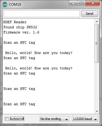
Serial comm window output for NDEF message read
Example #7: How to Change the Chip Select Pin From D10 to D9
Hardware Modification
- Scrape off the connection from the pads labeled "SS" and "D10" on the shield
- Connect/solder pads "SS" and "D9" on the shield.
You can then use the same code in the examples above but with pin 9 instead of 10 for the PN532 interface:
Code
PN532_SPI interface(SPI, 9); // create a SPI interface for the shield with the SPI CS terminal at digital pin 9
Example #8: Use Two NFC Shields With One Arduino Board
Hardware Modification
- Do the hardware modification described in Example #7 on one of the two shields.
- Stack both shields on the Arduino Board.
You may now create two separate NFC objects, one for each shield, as follows:
Code
|
|
 PN532_SPI interface_shield_1(SPI, 10); // create a SPI interface for the shield with the SPI CS terminal at digital pin 10
PN532_SPI interface_shield_2(SPI, 9); // create a SPI interface for the shield with the SPI CS terminal at digital pin 9

NfcAdapter nfc_shield_1 = NfcAdapter(interface_shield_1); // create an NFC adapter object for shield one
NfcAdapter nfc_shield_2 = NfcAdapter(interface_shield_2); // create an NFC adapter object for shield two
|