
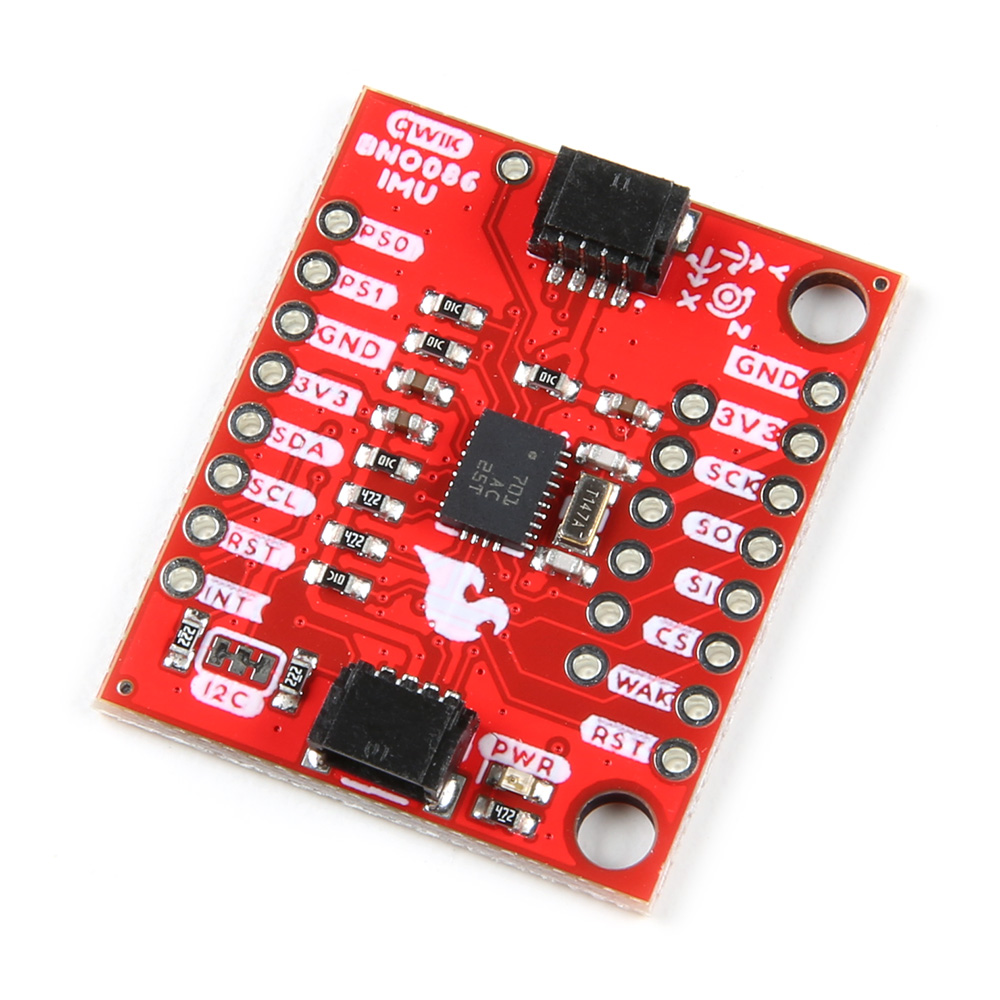
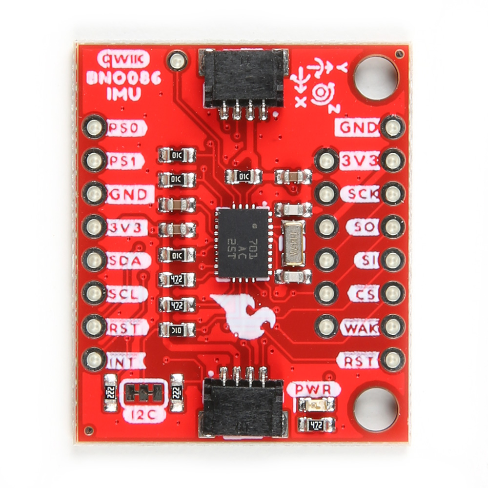
SparkFun VR IMU Breakout - BNO086 (Qwiic) - Red PCB


| รหัสสินค้า | AS20163 |
| หมวดหมู่ | วัดความเร่ง/ไจโร/IMU |
| ราคา | 2,285.00 บาท |
| สถานะสินค้า | พร้อมส่ง |
| จำนวน | ชิ้น |

รายละเอียดสินค้า
ชิป BNO080 ที่อยู่บนโมดูลนี้ ถูกออกแบบมาสำหรับใช้งานประเภท VR (Virtual Reality) หรือ Game หรืองานที่ต้องการความแม่นยำของทิศทางสูง ภายในชิปประกอบด้วย 3-axis accelerometer/gyro/magnetometer ประสิทธิภาพสูง ที่แพ็กรวมเข้ากับ 32-bit ARM Cortex M0+ และ Sensor Fusion Algorithm ตัวแรง ได้อย่างลงตัว ทำให้สามารถ ผลิต Rotation Vector Headings ที่มีความแม่นยำสูงออกมาได้ (ผิดพลาดไม่เกิน 2 องศา)
หมายเหตุ:
โมดูลนี้ต้องใช้คู่กับ สาย JST แบบที่ 1 click ดูสินค้า หรือ แบบที่ 2 click ดูสินค้า
ดู รายละเอียดการใช้งานและตัวอย่างโค๊ด ได้ที่ Click
Description:
Features:
- Operating Voltage
- 2.4V - 3.6V
- Typically 3.3V via Qwiic cable
- I2C (Default): Up to 400kHz
- SPI: Up to 3MHz
- UART: 3Mbps
- Rotation Vector
- Dynamic Error: 3.5°
- Static Error: 2.0°
- Gaming Rotation Vector
- Dynamic Error: 2.5°
- Static Error: 1.5°
- Dynamic Heading Drift: 0.5° / min
- Geomagnetic Rotation Vector
- Dynamic Rotation Error: 4.5°
- Static Rotation Error: 3.0°
- Gravity Angle Error: 1.5°
- Linear Acceleration Accuracy: 0.35m/s2
- Accelerometer Accuracy: 0.3m/s2
- Gyroscope Accuracy: 3.1° / sec
- Magnetometer Accuracy: 1.4µT
- 2x Qwiic Connection Ports
- I2C Address: 0x4B (default), 0x4A
- I2C Pull-Up Resistors (2.2kΩ)
- Power LED
- Jumpers
- Power LED
- I2C Pull-up Resistors
- Address Select
- Protocol Selection 0
- Protocol Selection 1
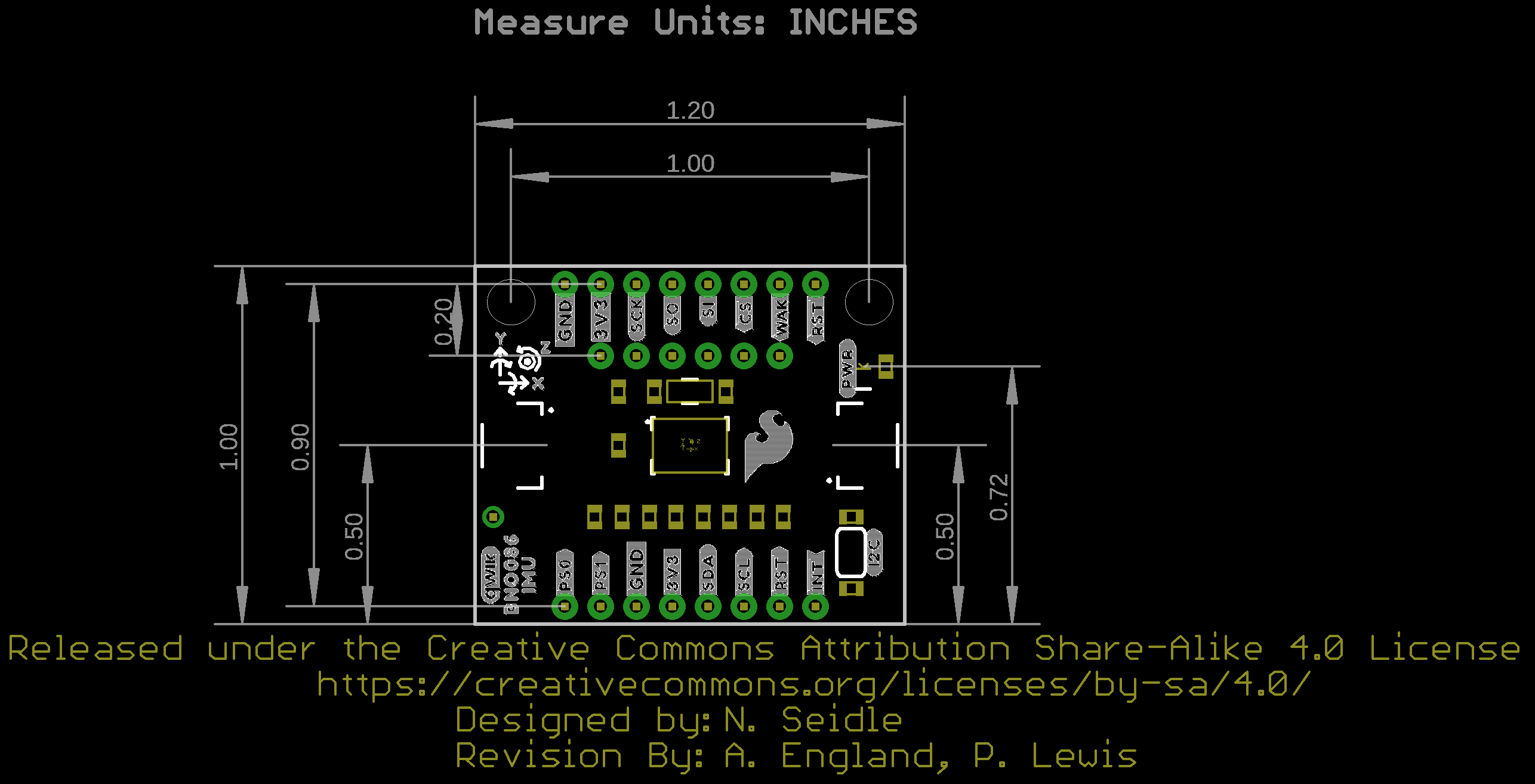
- Board Dimensions: 1.0in. x 1.2in. (25.4mm x 30.48mm)
- Weight: 3g
- Schematic
- Eagle Files
- Board Dimensions
- Hookup Guide
- BNO086
- Qwiic Page
- Arduino Library
- GitHub Hardware Repo
วิธีการชำระเงิน
ชำระเงินค่าสินค้าโดยการโอนเงินเข้าบัญชีธนาคาร KBANK, SCB, BBL,TMB
กรุณาเก็บหลักฐานการโอนเงินของท่านไว้เพื่อแจ้งการชำระเงินด้วยค่ะ
ท่านสามารถแจ้งการชำระเงินผ่านระบบอัตโนมัติได้โดย Click Link ข้างล่างค่ะ
https://www.arduitronics.com/informpayment
ชำระเงินผ่านธนาคาร


@rfm0967y
ติดต่อสอบถาม
Join เป็นสมาชิกร้านค้า
MEMBER
