
Gravity: Offline Edge AI Gesture & Face Detection Sensor – 5 Gestures, 10 Faces, 3m (Arduino/ RPi/ ESP32) - แท้ DFRobot
| รหัสสินค้า | AS30562 |
| หมวดหมู่ | โมดูลวัดสี กล้องและการมองเห็น Camera / Color / Vision |
| ราคา | 1,085.00 บาท |
| สถานะสินค้า | พร้อมส่ง |
| จำนวน | ชิ้น |

รายละเอียดสินค้า
ดูตัวอย่างการใช้งานและ arduino code ได้ที่ Click
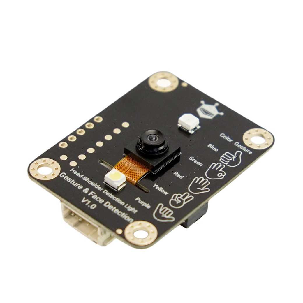
อุปกรณ์เซ็นเซอร์ AI นี้มีคุณสมบัติการตรวจจับใบหน้าและการรับรู้ท่าทางมือ 5 แบบ ซึ่งสามารถใช้งานได้ในระยะสูงสุด 3 เมตร เหมาะสำหรับสถานการณ์ที่ต้องการการใช้งานโดยไม่ต้องสัมผัส เช่น ในห้องนั่งเล่นที่สามารถเปลี่ยนช่องทีวีหรือปรับเสียงด้วยท่าทางมือขณะนอนบนโซฟาโดยไม่ต้องหารีโมท หรือในบ้านพักคนชราที่ผู้สูงอายุสามารถเรียกพยาบาลหรือปิดไฟข้างเตียงด้วยท่าทางมือ โดยไม่ต้องก้มไปกดปุ่ม ซึ่งช่วยลดความเสี่ยงในการเกิดอุบัติเหตุ นอกจากนี้ฟีเจอร์การตรวจจับใบหน้า (เหนือบ่า) ช่วยให้ระบบต่าง ๆ เช่น หน้าจอสาธารณะหรือเครื่องปรับอากาศสามารถปรับการทำงานอัตโนมัติตามตำแหน่งของผู้ใช้งาน เช่น เปิดเสียงเมื่อมีคนและปิดเมื่อไม่มี หรือปรับอุณหภูมิและลมให้เหมาะสมกับตำแหน่งของผู้ใช้ ช่วยประหยัดพลังงานและเพิ่มความสะดวกในการใช้งานด้วยการควบคุมท่าทางที่ง่ายดายและทันสมัย
In scenarios requiring contactless operation, it adeptly adapts to diverse needs.

The 5 types of hand gesture recognition, meanwhile, focus on "medium-free remote control": no need to find remotes or touch devices—simply make a "👍" towards the target to turn on lights, or a "👌" to adjust temperature. Whether in home life or public settings, a simple gesture suffices to complete the operation, blending convenience with a strong sense of technology.
Features
-
AI Recognition Performance: Offline solution, rapidly recognizing 5 hand gestures within 3 meters with high accuracy
-
Facial Detection: Supports detection of areas above the shoulders, outputting quantity, position coordinates, and recognition scores
-
Communication Methods: Two data communication modes—I2C and UART
-
Voltage Compatibility: Compatible with 3.3V/5V levels and supply voltages
-
Development Support: Supports MakeCode and Mind + graphical programming
Application
-
Contactless control of information screens in public areas
-
Stage performances
-
Home appliance control
-
Music playback control
-
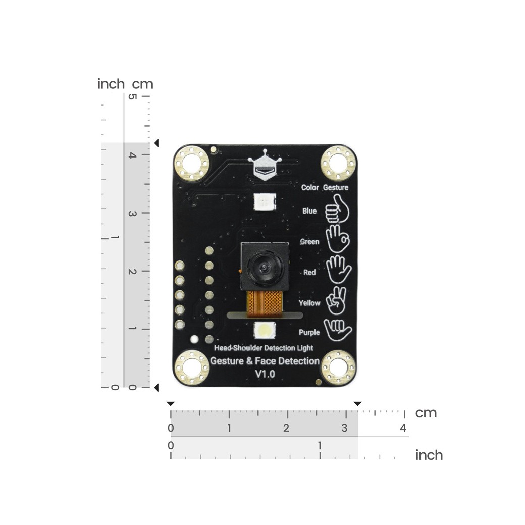
Dimension Diagram
Dimension Diagram

Physical Dimensions
- PCB Dimensions: 42m*32mm
- Mounting Hole Spacing: 25mm*35mm
- Mounting Hole Diameter: 3.1mm
Specifications
| Parameter Category | Specific Parameters |
|---|---|
| Power Parameters | Supply Voltage: 3.3V-5V Level Voltage: 3.3V Operating Current: 100mA |
| Interface Parameters | Communication Interface: PH2.0-4P/2.54mm pin header holes Communication Methods: I2C/UART I2C/UART Default Address: 0x72 Default UART Baud Rate: 9600 UART Communication Protocol: modbus Interrupt Interface: 2.54mm pin header hole |
| Recognition Parameters | Types of Gesture Recognition: 5 - Good 👍 - OK 👌 - Stop 🤚 - Victory ✌️ - Call me 🤙 Recognition Distance (Gesture/Face): 0.5-3 meters Facial Recognition Range: Area above the human shoulders Maximum Number of Recognizable Faces: Up to 10 Facial Recognition Score: 0-100 Facial Position Coordinate Range: 0-640 Interrupt Output: Low level output upon gesture recognition Camera Field of View: D=85° Camera Focal Length: 1.56mm |
| Display Parameters | Gesture Indicator Lights: RGB lights - Blue for 👍 - Green for 👌 - Red for 🤚 - Yellow for ✌️ - Purple for 🤙 Facial Indicator Light: Single LED (lit = presence detected, unlit = no presence) |
Function Diagram
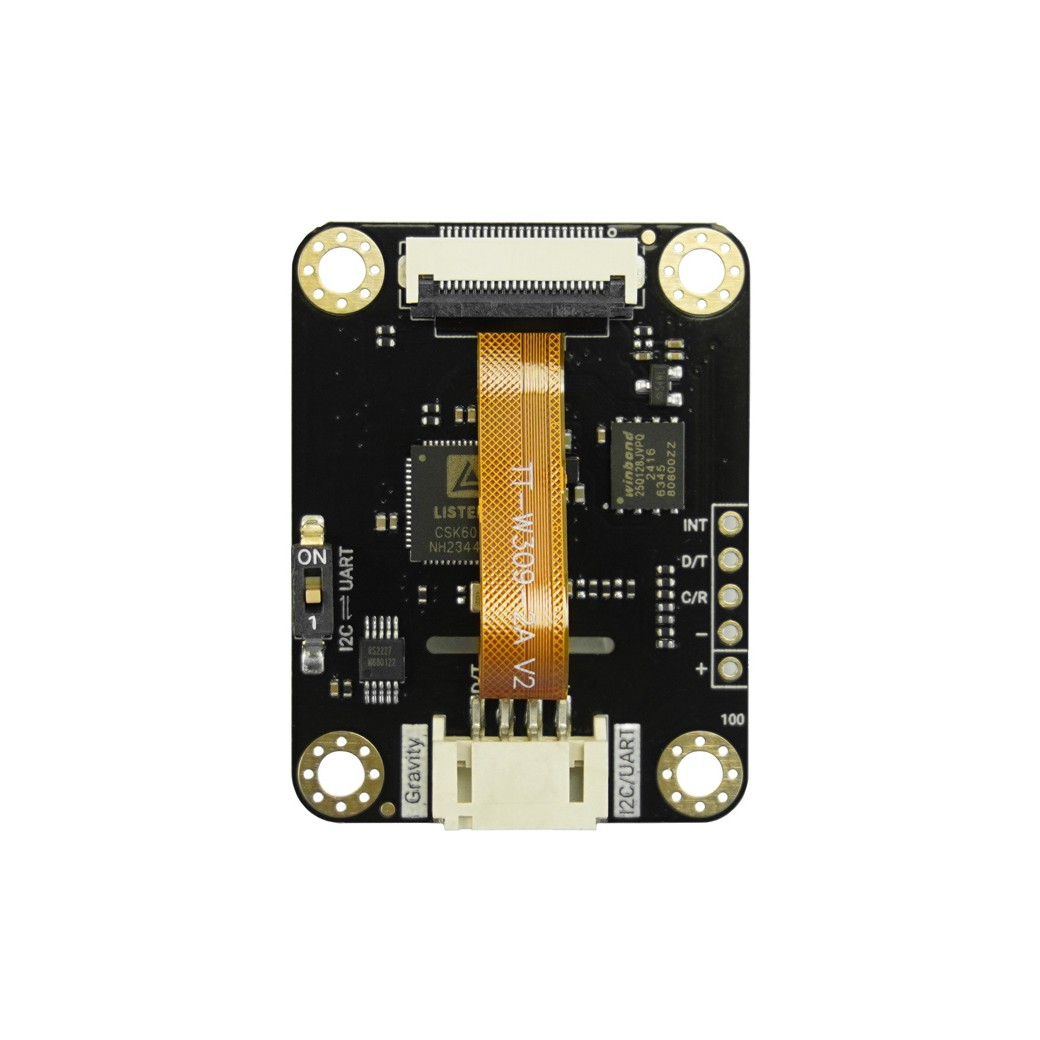
| Label | Name | Function Description |
|---|---|---|
| ① | D/T | I2C data line SDA or UART transmission terminal TXD (3.3V level) |
| ② | C/R | I2C clock line SCL or UART reception terminal RXD (3.3V level) |
| ③ | GND | Power supply negative pole |
| ④ | VCC | Power supply positive pole (3.3~5.5V) |
| ⑤ | INT | Interrupt output, low level output upon recognition of any gesture |
| ⑥ | I2C/UART | I2C/UART communication mode selection switch |
| ⑦ | Head-Shoulder Indicator Light | Illuminates steadily when the camera detects a face, extinguishes when the person leaves |
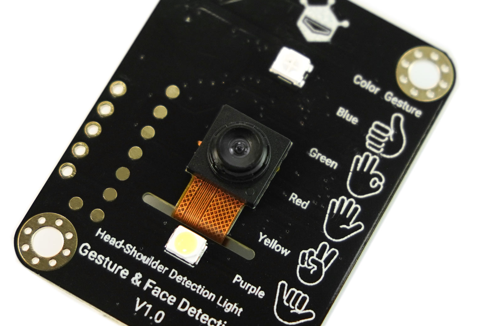
| ⑧ | Gesture Indicator Light | Illuminates in colors corresponding to the 5 predefined gestures |
Detailed Explanation of Core Functions
1. Gesture Recognition Function
Supported Gestures and Corresponding Information
| Action Example | Common Name | Gesture Illustration | Indicator Light Color | Corresponding Program Value |
|---|---|---|---|---|
| Thumb raised | Good | 👍 | Blue | 1 |
| Middle, ring, and little fingers extended, with index finger and thumb tip touching (OK gesture) | OK | 👌 | Green | 2 |
| Palm spread outward | Stop | 🤚 | Red | 3 |
| Index and middle fingers extended | Victory | ✌️ | Yellow | 4 |
| Thumb and little finger extended | Call me | 🤙 | Purple | 5 |
Core Capabilities
- Capable of real-time detection of 5 gestures (👍, 👌, 🤚, ✌️, 🤙) with stable recognition within 3 meters; upon recognition, real-time feedback is provided via corresponding colored indicator lights (e.g., blue for a good), while outputting the gesture type and recognition score.
Frequently Asked Questions
Q: What does the gesture score signify, and what score constitutes a valid recognition?
A: The gesture recognition result outputs a score ranging from 0 to 100. By default, the program a score of ≥60 as a valid gesture (which will trigger the function). A higher score indicates a greater "similarity" between the current action and the standard gesture; for instance, a score of 80 or above generally confirms the target gesture. A score below 30 is often due to suboptimal recognition conditions (such as an unstandardized gesture, excessive distance beyond the effective range, or ambient light interference), in which case accurate gesture recognition is improbable.
Q: What is the range of gesture recognition distance, and what considerations apply when using it at different distances?
A:
- Recognition Range: Supports recognition within 0.5-3 meters. Prior to recognizing gestures, ensure that the area above the shoulders is fully within the camera's field of view and detected (facial indicator light illuminated). If the distance is too close (<0.5 meters), the area above the shoulders may exceed the camera's capture range, resulting in recognition failure;
- Optimal Distance (1-2 meters): Within this range, the camera achieves a balance between "comprehensive frame coverage" and "clarity of feature details," enabling precise capture of gestures with optimal recognition accuracy and response speed;
- Maximum Distance (≤3 meters): More susceptible to environmental interference. Obstructions (such as crowds or furniture) or complex lighting (direct glare/dimness) may impair recognition performance. It is advisable to utilize the 3-meter maximum distance in open, evenly lit environments, prioritizing an unobstructed lens and clear imagery.
2. Facial Detection Function (Including the Area Above the Shoulders)
Core Capabilities
- Capable of detecting the "facial range" with feedback via the facial indicator light (lit = presence detected, unlit = no presence).

- Capable of detecting the number of faces (up to 10), and real-time output of the number of faces, the coordinates of the face with the highest score, and the corresponding recognition score.
Frequently Asked Questions
Q: How to interpret the facial coordinate range, and what is its significance?
A: The X/Y coordinate range of the face is 0-640, corresponding to physical position coordinates within the camera's field of view. The numerical value is directly correlated with the actual position: a larger X value indicates the face is further to the right in the camera's view; a larger Y value indicates it is further downward (with the coordinate origin at the top-left corner of the view). For example, (320,320) corresponds to the exact center of the view, facilitating intuitive localization of the face within the frame and enabling position-based functions such as servo tracking.
Q: What does the facial score represent, and what score confirms a face?
A: The facial recognition result outputs a score ranging from 0 to 100. The program defaults to a reference threshold of 60, with a higher score indicating a greater likelihood that the region is a face. For example, a score of 90 suggests a high probability of it being a face.
Q: When multiple faces are present simultaneously, what rule governs the return of coordinates?
A: Currently, simultaneous return of coordinates for multiple faces is not supported; only the coordinates of the face with the highest recognition score (highest score = clearest view, most face-like) will be returned.
Q: When multiple faces and gestures are detected simultaneously, what is the scoring correspondence rule?
A: When multiple faces and gestures are detected, the score corresponds by default to the target with the highest gesture score (i.e., the target with the clearest gesture).
Q: What is the logical sequence of gesture and facial detection, and what precautions apply during use?
A: The camera first detects whether a face is recognized, then checks for the presence of the 5 gestures. Ensure that both the face and gestures are within the camera's detection range (i.e., perform the corresponding gesture when the facial indicator light is illuminated).
Tutorial for Using Arduino IDE
Through the following tutorial, you will master the basic usage and advanced applications of the SEN0626 AI Visual Gesture/Face Tracking Sensor in the Arduino IDE environment, specifically including: reading sensor data via both I2C and UART communication methods to understand the actual effects of gesture recognition and face detection; and through two examples of a dazzling LED ring and a human-tracking fan, learning how to combine the sensor with other devices to achieve complex functions (the following tutorial uses controllers such as FireBeetle 2 ESP32-E, DFRduino UNO R3 paired with the SEN0626 sensor as examples).
Basic Tutorial
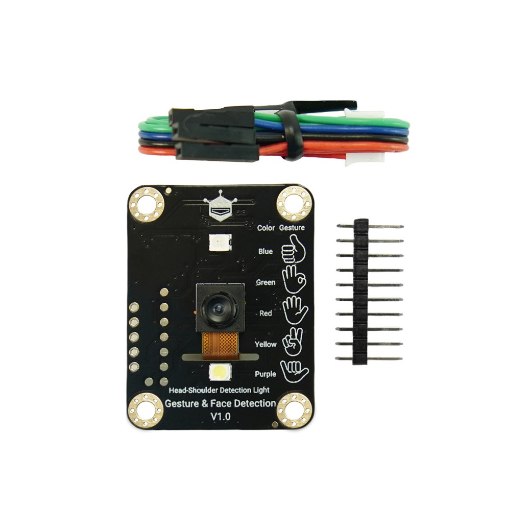
- Hardware Preparation
- Software Preparation
- Arduino IDE Click to download Arduino IDE
- Download and install DFRobot_GestureFaceDetection
- Download and install DFRobot_RTU
Reading Data via I2C
We can make the connections according to the diagram below:
- Wiring Diagram

- Sample Code
- Step 1: Connect the sensor to the ESP32-E controller according to the wiring diagram above, and switch the communication mode selection switch on the sensor to the I2C side.
- Step 2: Open Arduino IDE, copy the following code and upload it to the ESP32-E.
- Step 3: Open the serial monitor in Arduino IDE, set the baud rate to 115200, and observe the serial print results.
Results
Output content of the serial monitor:

Interpretation:
- First line: Face detection data
x = 291, y = 330: Indicates the position coordinates of the detected face (area above the shoulders) in the camera's field of view (range 0-640; the larger the value, the closer to the right/bottom of the field of view);score = 74: Face recognition score (0-100), with a higher score indicating more accurate recognition (a score ≥60 is considered valid).
- Second line: Gesture detection data
gesture 2: Indicates that the recognized gesture type is "OK" (corresponding to program value 2, refer to the gesture comparison table in "Detailed Explanation of Core Functions");score = 91: Gesture recognition score (0-100), with a higher score indicating a more standard gesture (a score ≥60 is considered valid). At this time, the gesture indicator light will synchronously light up green (corresponding to the "OK" gesture).
Note:
The above two lines of information will only be output when the sensor detects both a face (area above the shoulders) and a gesture simultaneously; if no face is detected, there will be no output from the serial port.
Reading Data via UART
We can make the connections according to the diagram below
- Wiring Diagram

- Sample Code
- Step 1: Connect the sensor to the ESP32-E controller according to the wiring diagram above, and switch the communication mode selection switch on the sensor to the UART side.
- Step 2: Open Arduino IDE, copy the following code and upload it to the ESP32-E.
- Step 3: Open the serial monitor in Arduino IDE, set the baud rate to 115200, and observe the serial print results.
Results
Output content of the serial monitor:

Interpretation:
- First two lines: Device identity information
Product ID: 626: The product number of the sensor (corresponding to 0x3343 in hexadecimal);Vendor ID: 13123: The vendor number (corresponding to 0x0272 in hexadecimal).
- Third line: Face detection result
Faces detected: 1: Indicates that 1 face (area above the shoulders) is currently detected, and the face indicator light is on steadily at this time;- If there is no one, it will display
Faces detected: 0, and the indicator light will turn off synchronously.
The face detection information is refreshed every 1.5 seconds, providing an intuitive feedback of the detection result.
Advanced Tutorial
Dazzling LED Ring
Through this tutorial, you will learn how to combine the AI Visual Gesture/Face Tracking Sensor with a WS2812B RGB LED ring, using the sensor to achieve contactless control of the LED ring's color, creating a dazzling LED ring device that changes color with gestures.
Hardware Preparation
- DFR0868 Beetle ESP32-C3 ×1
- FIT0676 93-LED/6-Ring WS2812B RGB ×1
- SEN0626 AI Visual Gesture/Face Tracking Sensor ×1
Software Preparation
- Arduino IDE Click to download Arduino IDE
- Download and install DFRobot_GestureFaceDetection
- Download and install DFRobot_RTU
- Download and install FastLED
Wiring Diagram
We can make the connections according to the diagram below

Sample Code
- Step 1: Connect the sensor, WS2812B LED ring, and ESP32-C3 controller according to the wiring diagram, and switch the sensor's communication mode switch to the I2C side.
- Step 2: Open Arduino IDE, copy the following code and upload it to the ESP32-C3.
Results
When the sensor detects a face (area above the shoulders), the LED ring will synchronously change color according to the gesture you make:
- Gesture 1 (Good) → Blue;
- Gesture 2 (OK) → Green;
- Gesture 3 (Stop) → Red;
- Gesture 4 (Victory) → Yellow;
- Gesture 5 (Call me) → Purple.
When no face is detected, the LED ring automatically turns off, achieving the intelligent effect of "lights on when someone is present, color controlled by gestures".
Face-Tracking Fan
Through this tutorial, you will learn how to integrate the AI Visual Gesture/Face Tracking Sensor with a DC motor fan and a servo motor to achieve two core functions: controlling the fan's start and stop via gestures, while enabling the fan to automatically rotate and track the face position, creating an intelligent fan device that "delivers wind where the person is and is controllable via gestures".
Hardware Preparation
- DFR0216 DFRduino UNO R3 ×1
- DFR0265 Gravity: IO Sensor Expansion Board V7.1 ×1
- DFR0411 Gravity: 130 DC Motor Fan ×1
- SER0056 2Kg 300° Clutch Servo ×1
- AI Visual Gesture/Face Tracking Sensor ×1
Software Preparation
- Arduino IDE Click to download Arduino IDE
- Download and install DFRobot_GestureFaceDetection
- Download and install DFRobot_RTU
- How to install libraries
Wiring Diagram
Connections can be made according to the diagram below:

Sample Code
- Step 1: Connect the sensor, DFRduino UNO R3 controller, IO sensor expansion board, fan, and servo according to the wiring diagram, and switch the sensor's communication mode switch to the I2C side.
- Step 2: Open Arduino IDE, copy the following code and upload it to the DFRduino UNO R3.
Results
When the sensor detects a face (area above the shoulders), the system activates the following linked effects:
- Gesture-Controlled Fan
- Making the "OK" gesture (corresponding to gesture type 2): The fan turns on immediately at maximum power without the need to touch a switch;
- Making the "Number 5" gesture (corresponding to gesture type 3): The fan automatically turns off, achieving contactless start-stop control.
- Real-Time Face Position Tracking: The servo motor will drive the fan, adjusting the angle in real time according to the X-coordinate of the face in the camera's field of view (range 0-620):
- When the face moves left (X value decreases), the servo angle decreases synchronously (range 10°-170°), and the fan turns left;
- When the face moves right (X value increases), the servo angle increases synchronously, and the fan turns right; the entire process is smooth and continuous, achieving the precise following effect of "wherever the person goes, the fan follows".
- Debugging Feedback: The serial monitor outputs the X-coordinate of the face and the currently recognized gesture type in real time (e.g., "300", "2"), facilitating observation of the device's operating status and debugging optimization.
Note: Please check the tracking fan structure file in more downloads.
API Functions
Graphical Programming Tutorial
1. Mind+ (Based on Scratch3.0): Reading Face/Gesture Data with Building Blocks
No coding is required. By dragging and dropping graphical building blocks, you can make the sensor output the number of faces, position coordinates, and the types of recognized gestures (such as "thumbs-up", "OK", etc.).
Operation Steps:
- Download and Install the Software: Click Download Mind+ and follow the prompts to complete the installation (refer to the Mind+ Basic Installation Tutorial).
- Select Device and Add Extension:
- Open Mind+, switch to "Upload Mode", and select "Arduino Uno" in "Extensions" → "Main Control Board";
- Click "User Library", paste the link:
https://gitee.com/zhangtang6677/ext-gestureFaceDetectionSensor.git, search for and add the "Gesture and Face Tracking Sensor" extension.
- Graphical Programming: Drag modules from the left building block area (such as "Read Number of Faces", "Read Gesture Type", etc.) to form a simple program (refer to the example diagram).

-
Upload and View Results:
- Connect the sensor to the computer with a data cable, "Connect Device" in Mind+ and select the corresponding port;
- Click "Upload to Device", and after completion, open the "Serial Monitor" to see the real-time output of face, gesture, and face coordinate data (such as "Number of faces: 1", "Gesture: 2 (OK gesture)").
2. MakeCode (micro:bit Platform): Graphical Implementation of Face/Gesture Detection
On the micro:bit development board, program with graphical building blocks to enable the sensor to detect the presence of a face, recognize gesture types, and display the results on the device, which is suitable for fun interactive projects with micro:bit.
Operation Steps:
- Open the Programming Platform: Enter the MakeCode official website in the browser, click "New Project" and name it (e.g., "Face and Gesture Detection").
- Load the Sensor Library:
- Click "Settings" in the upper right corner → "Extensions", paste the link in the search box:
https://github.com/DFRobot/pxt-DFRobotGestureFaceDetection, and load the extension library.
- Click "Settings" in the upper right corner → "Extensions", paste the link in the search box:
- Graphical Programming: Drag modules from the left building block area (such as "Get Number of Faces", "Get Face X Coordinate") to form a program (refer to the example diagram).

-
Download and View Results:
- Click "Download" to save the program to the computer and transfer it to the micro:bit development board;
- Connect the sensor to the micro:bit, open the "Show data" window, and you can see the real-time detection results (such as "Number of faces: 1", "Gesture: 2 (OK gesture)").
General Notes:
- In the Mind+ and MakeCode graphical programming environments, the sensor only supports the I2C communication mode and does not support the UART mode for the time being. Please switch the sensor's communication mode switch to the I2C side to ensure proper use.
- For supported gestures and corresponding information, refer to the "Detailed Explanation of Core Functions" section above in the Wiki.
- If no data is output, check whether the device connection is secure and whether the extension library is added correctly.
Modbus Register Definitions
For customizing device addresses, querying firmware versions, or adjusting core parameters, the following registers can be utilized (suitable for advanced development scenarios):
| Register Type | Device Address (Decimal) | Modbus Address Offset (Hexadecimal) | Name | Read/Write | Data Range | Default Value | Description |
|---|---|---|---|---|---|---|---|
| Input Register | 3001 | 0x0000 | VID | R | 0x0000-0xFFFF | 0x0272 | VID (Vendor ID) |
| Input Register | 3002 | 0x0001 | PID | R | 0x0000-0xFFFF | 0x3343 | PID (Product ID) |
| Input Register | 3003 | 0x0002 | Hardware Version | R | 0x0000-0xFFFF | 0x1000 | Hardware version: 0x1000 represents V1.0.0.0 |
| Input Register | 3004 | 0x0003 | Software Version | R | 0x0000-0xFFFF | 0x1000 | Software version: 0x1000 represents V1.0.0.0 |
| Input Register | 3005 | 0x0004 | Number of Faces | R | 0x0000-0x000A | 0x0000 | Number of faces detected by the sensor, up to 10 |
| Input Register | 3006 | 0x0005 | Face X Coordinate | R | 0x0000-0x000A | 0xFFFF | X coordinate of the detected face. 0xFFFF: no face detected. X coordinate range: 0-640 |
| Input Register | 3007 | 0x0006 | Face Y Coordinate | R | 0x0000-0x000A | 0xFFFF | Y coordinate of the detected face. 0xFFFF: no face detected. Y coordinate range: 0-640 |
| Input Register | 3008 | 0x0007 | Face Score | R | 0x0000-0x0064 | 0x0000 | Face score. 0% - 100% corresponds to values 0-100 |
| Input Register | 3009 | 0x0008 | Gesture Type | R | 0x0000-0x0005 | 0x0000 | Gesture type: - 0x0000: other gestures; - 0x0001: Good 👍; - 0x0002: OK 👌; - 0x0003: STOP 🤚; 0x0004: Victory ✌️; - 0x0005: Call me 🤙 |
| Input Register | 3010 | 0x0009 | Gesture Score | R | 0x0000-0x0064 | 0x0000 | Gesture score. 0% - 100% corresponds to values 0-100 |
| Holding Register | 4001 | 0x0000 | Device Address | R/W | 0x0001-0x00F7 | 0x0072 | Module device address (1-247) [When the sensor address is unknown, write register operations can be performed via the broadcast address 0x00, and the sensor will not output data at this time]. DFRobot assigns different addresses to each product at the factory. Saved when power is off, takes effect immediately |
| Holding Register | 4002 | 0x0001 | Serial Port Parameter Control Register 1 | R/W | 0x0000-0xFFFF | 0x0004 | Module baud rate: - 0x0001-1200; - 0x0002-2400; - 0x0003-4800; - 0x0004-9600 (default); - 0x0005-14400; - 0x0006-19200; - 0x0007-38400; - 0x0008-57600; - 0x0009-115200; - 0x000A-230400; - 0x000B-460800; - 0x000C-921600; - Other-9600. If modified successfully, it will reply at the current baud rate, and switch to the new baud rate after reply. Saved when power is off, takes effect after restart. The device is recommended to work below 115200 |
| Holding Register | 4004 | 0x0003 | Set Target Face Detection X Coordinate Range Threshold | R/W | 0x0000-0x0064 | 0x0064 | Value range: 0-100, the smaller the value, the narrower the detection range. 100 represents the entire visible range of the camera |
| Holding Register | 4005 | 0x0004 | Set Target Face Detection Score Threshold | R/W | 0x003C-0x0064 | 0x003C | Value range: 60-100, representing 60%-100%. Default value: 60 |
| Holding Register | 4006 | 0x0005 | Set Gesture Detection Score Threshold | R/W | 0x003C-0x0064 | 0x003C | Value range: 60-100, representing 60%-100%. Default value: 60 |
Note:
- The default device address is 0x0072. If the address is modified, the I2C address will be updated accordingly.
- The face detection range is the area above the human shoulders.
Common Modbus-RTU Function Codes:
| Function Code | Name | Function |
|---|---|---|
| 0x03 | Read Multiple Registers | Read integers, characters, status words, floating-point numbers (read N words) - read holding registers, byte operation |
| 0x04 | Read Input Registers | Read integers, status words, floating-point numbers (read N words) - read input registers, byte operation |
| 0x06 | Write Single Holding Register | Write integers, characters, status words, floating-point numbers (write one word) - write holding registers, byte operation |
| 0x10 | Write Multiple Holding Registers | Write multiple holding registers - load specific binary values into a series of consecutive holding registers |
Input registers and holding registers can be read and written via the above commands.
Register Read/Write Examples
Hardware Preparation
Recommended Serial Debugging Tools and Downloads
For serial port-related debugging work, professional serial debugging tools are required. Here are several commonly used and feature-rich tools recommended for you:
- xcom Serial Debug Assistant V2.0: An efficient and easy-to-use serial communication assistant. Available at this link.
- SSCOM3.2 Serial Assistant: Designed specifically for embedded development, IoT communication, and daily serial debugging. Download address is project repository.
Example 1: Read Number of Faces (Read Input Register Operation)
Function: Read the number of faces currently detected by the sensor via the Modbus RTU protocol.
Sending Command and Analysis
| Field Name | Hexadecimal Value | Description |
|---|---|---|
| Device Address | 72 | Sensor default UART address 0x72 |
| Function Code | 4 | Read input registers (fixed command) |
| Starting Register Address | 00 04 | Register address corresponding to the number of faces |
| Number of Registers | 00 01 | Read 1 register (only the number of faces) |
| CRC Check | 7B 08 | Command check value (to ensure transmission correctness) |
Complete sending command: 72 04 00 04 00 01 7B 08
Operation Steps
-
Hardware Connection: Connect the sensor to the host (computer) via the RainbowLink USB protocol converter, and switch the sensor communication mode to UART.
-
Parameter Configuration: Set parameters in the serial debugging tool (must be consistent with the sensor):
- Baud rate: 9600 (default)
- Data bits: 8 bits
- Stop bits: 1 bit
- Parity: None
-
Send Command: Enter the above hexadecimal command in the "Send Area" of the debugging tool, check "Send in Hexadecimal" and send.
Return Data and Analysis
After receiving the command, the sensor returns the number of faces data, as shown in the example below:
| Field Name | Hexadecimal Value | Description |
|---|---|---|
| Device Address | 72 | Consistent with the device address in the sending command |
| Function Code | 4 | Confirm execution of "read input register" operation |
| Number of Bytes | 2 | Total number of returned data bytes (2 bytes) |
| Read Data | 00 01 | Indicates that 1 face is currently detected (the value corresponds to the number of faces) |
| CRC Check | 7D 3B | Check value of the returned data |
Complete return data: 72 04 02 00 01 7D 3B
Schematic diagram as follows:

Example 2: Modify Module Baud Rate (Write Holding Register Operation)
Function: Modify the UART baud rate of the sensor via the Modbus RTU protocol (default 9600, customizable).
Sending Command and Analysis
| Field Name | Hexadecimal Value | Description |
|---|---|---|
| Device Address | 72 | Sensor default address 0x72 |
| Function Code | 6 | Write holding register (fixed command) |
| Starting Register Address | 00 01 | Register address corresponding to baud rate configuration |
| Written Data | 00 09 | Corresponding to baud rate 115200 bps (see the register table for the relationship between values and baud rates) |
| CRC Check | 13 0F | Command check value |
Complete sending command: 72 06 00 01 00 09 13 0F
Operation Steps
- Hardware connection and basic parameter configuration are the same as "Reading the number of faces" (the current default baud rate 9600 must be used to send commands).
- After sending the above command, if the returned data is consistent with the sending command, it indicates that the baud rate modification request has been received by the device.
Return Data and Analysis
Complete return data: 72 06 00 01 00 09 13 0F
| Field Name | Hexadecimal Value | Description |
|---|---|---|
| Device Address | 72 | Consistent with the sending command |
| Function Code | 6 | Confirm execution of "write holding register" operation |
| Starting Register Address | 00 01 | Baud rate configuration register address |
| Written Data | 00 09 | Confirm baud rate set to 115200 bps |
| CRC Check | 13 0F | Check value of the returned data |
Note:
- The baud rate modification takes effect only after the sensor is powered off and restarted;
- After restart, the serial debugging tool's baud rate must be modified to 115200 synchronously, otherwise communication cannot continue.

More Downloads
วิธีการชำระเงิน
ชำระเงินค่าสินค้าโดยการโอนเงินเข้าบัญชีธนาคาร KBANK, SCB, BBL,TMB
กรุณาเก็บหลักฐานการโอนเงินของท่านไว้เพื่อแจ้งการชำระเงินด้วยค่ะ
ท่านสามารถแจ้งการชำระเงินผ่านระบบอัตโนมัติได้โดย Click Link ข้างล่างค่ะ
https://www.arduitronics.com/informpayment
ชำระเงินผ่านธนาคาร


@rfm0967y
ติดต่อสอบถาม
Join เป็นสมาชิกร้านค้า
MEMBER
