
FireBeetle 2 ESP32-P4 AI Vision Board (360MHz RISC-V, MIPI CSI/DSI, Wi-Fi 6) - แท้จาก DFRobot
| รหัสสินค้า | BA00310 |
| หมวดหมู่ | WiFi ESP32-P4 |
| ราคา | 685.00 บาท |
| สถานะสินค้า | พร้อมส่ง |
| จำนวน | ชิ้น |

รายละเอียดสินค้า
Accelerate Edge AI and multimedia projects with the FireBeetle 2 ESP32-P4. This compact, highly-integrated platform combines a 360MHz dual-core RISC-V CPUwith nativeMIPI-CSI/DSIinterfaces for high-resolution video, anonboard microphone, and Wi-Fi 6 connectivity. It's engineered to be the ideal core for building AI cameras, interactive GUIs, and smart home panels, providing a powerful yet streamlined foundation to move quickly from concept to high-performance prototype.
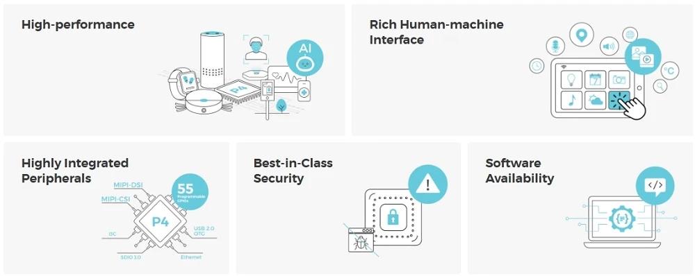
High-Performance AI Core
Native Multimedia Powerhouse
The board excels at multimedia processing thanks to its native MIPI-CSI and MIPI-DSI interfaces, which allow for the direct connection of high-resolution cameras and displays, eliminating the need for complex adapter boards. With onboard hardware accelerators for H.264 video and JPEG encoding, it can efficiently handle video streams up to 1080p, making it the perfect core for AI cameras and interactive GUIs. Furthermore, the interfaces are pin-compatible withRaspberry Piperipherals, greatly simplifying component sourcing.
Highly Integrated, Compact Design
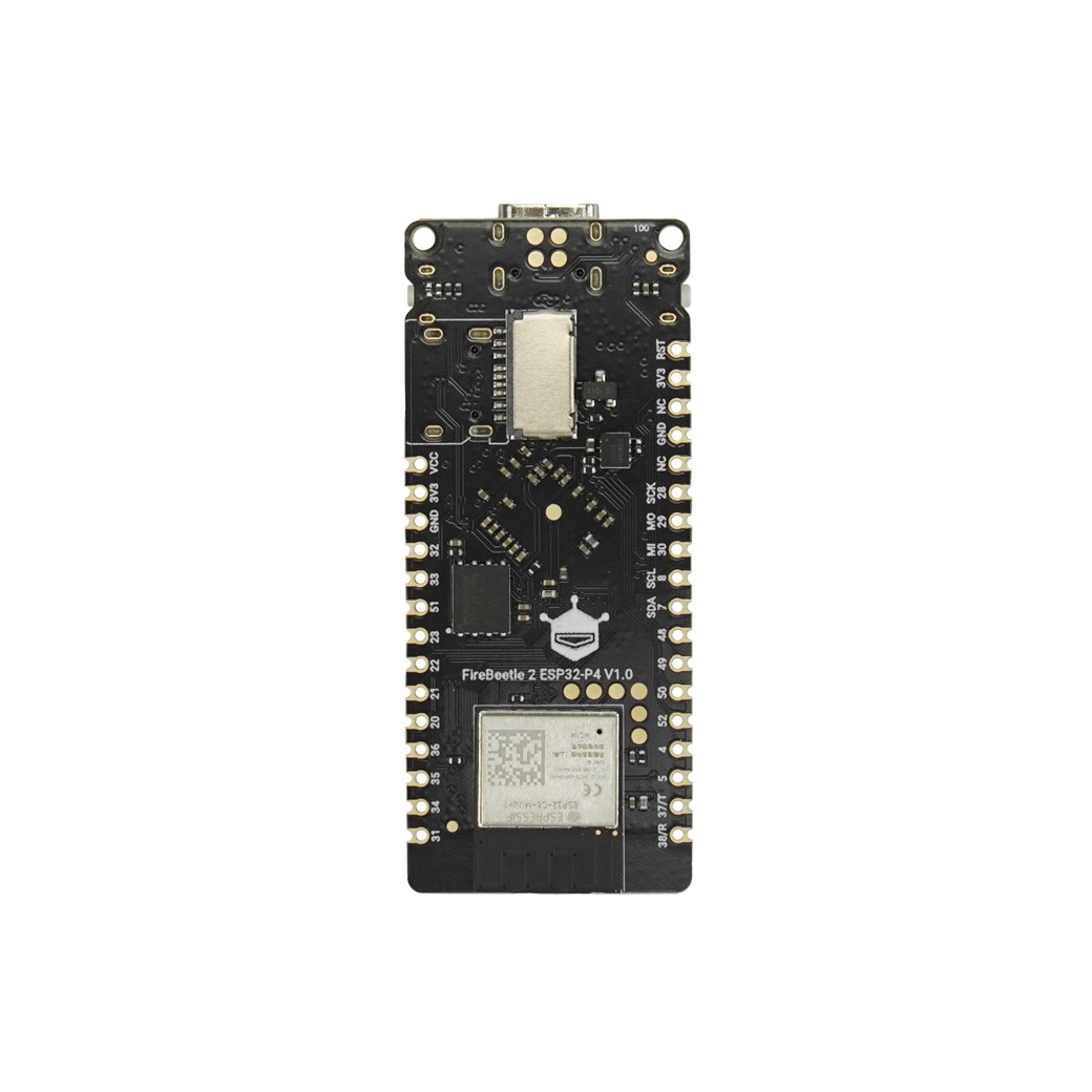
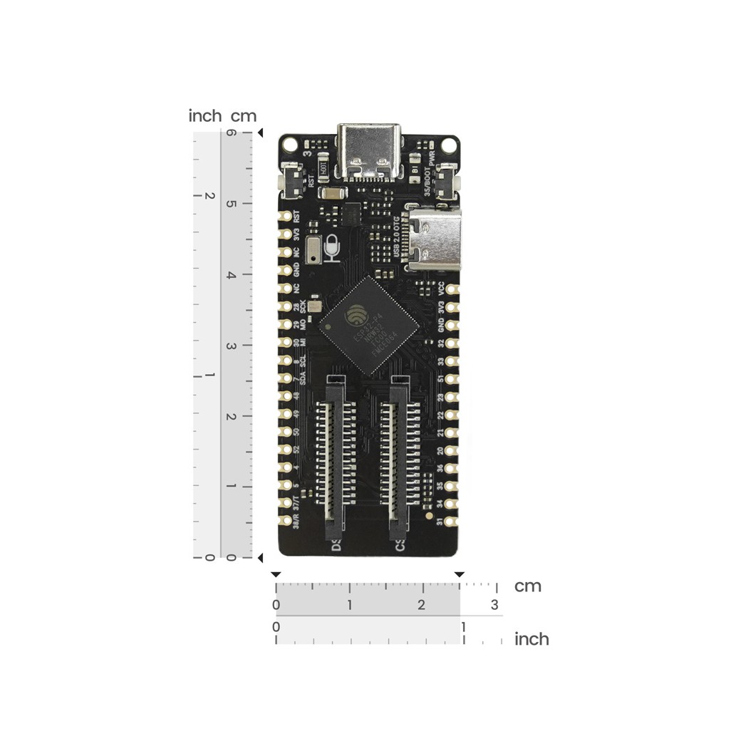
Beyond its processing power, the FireBeetle 2's value lies in its thoughtful integration within a minimal 25.4 x 60mm footprint. It features a built-in PDM digital microphone for voice-activated applications and a TF card slot for expansive local data storage. This high level of integration reduces the need for external modules, simplifies the overall product design, and is ideal for creating compact, space-constrained devices.
Future-Proof Connectivity
Equipped with an onboard ESP32-C6 co-processor, the FireBeetle 2 supports the latest Wi-Fi 6 standard. This provides higher throughput, lower latency, and improved performance in congested network environments—critical for data-intensive AIoT applications. This is complemented by stable Bluetooth 5 (LE) for versatile peripheral communication.
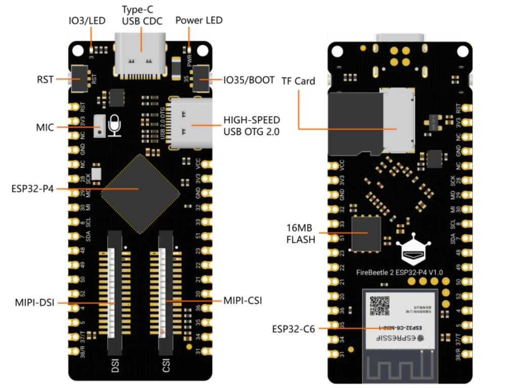
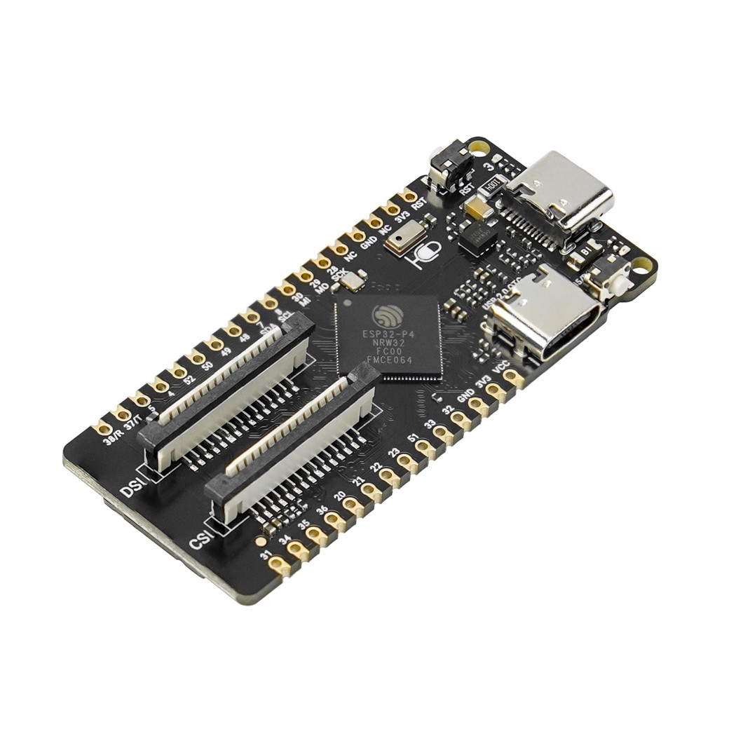
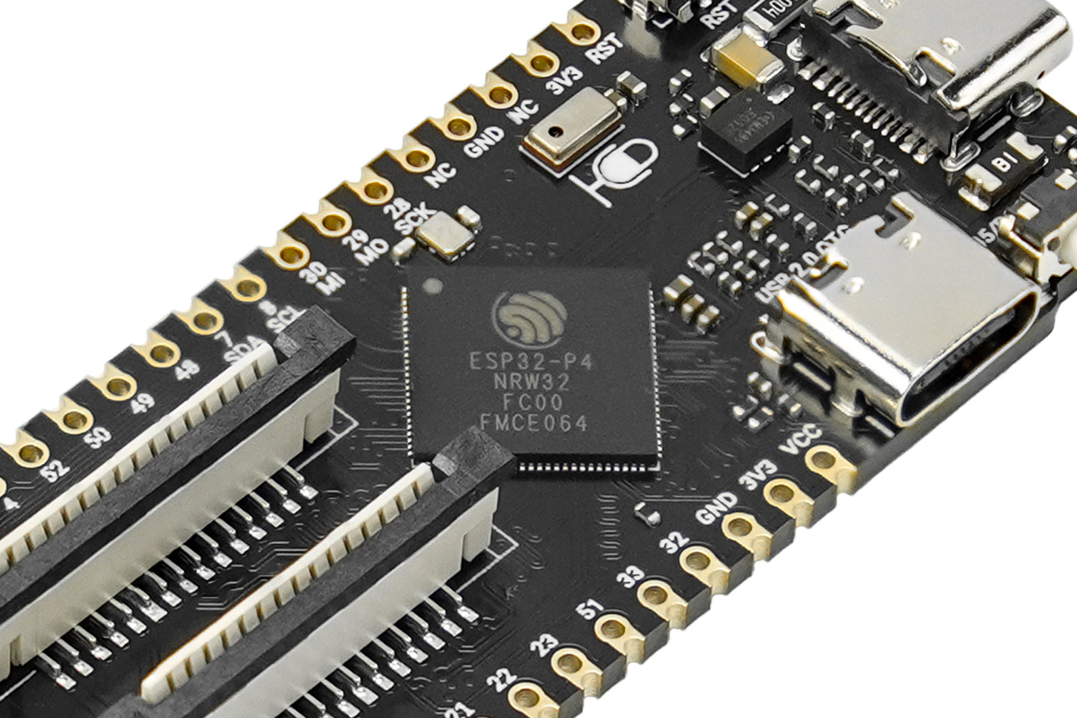
The diagram above highlights the key components and interfaces of the FireBeetle 2 ESP32-P4. Refer to the list below for detailed descriptions of the main features:
- MIPI-DSI Interface: 2-lane MIPI Display port, pin-compatible with Raspberry Pi displays for easy sourcing and setup.
- MIPI-CSI Interface: 2-lane MIPI Camera port, pin-compatible with Raspberry Pi cameras, ideal for AI vision projects.
- ESP32-C6 Co-processor: Provides powerful and modern Wi-Fi 6 and Bluetooth 5 (LE) connectivity, connected to the main P4 chip via SDIO.
- High-Speed USB OTG (Type-C): A USB 2.0 High-Speed port for fast data transfer, supporting OTG to connect to other USB devices.
- USB CDC & Power (Type-C): The primary port for programming, debugging (via serial), and powering the board.
- PDM Microphone: An onboard digital microphone, allowing for direct development of voice recognition and other audio-based AI applications.
- TF Card Slot: A MicroSD card slot for storing AI models, images, and data logs.
- BOOT & RST Buttons: Standard buttons for resetting the board and entering the firmware download mode.
For a complete, pin-by-pin functional description, please refer to the Product Wiki.
Looking for an easier start?
For rapid prototyping without breadboards or soldering, consider the FireBeetle 2 ESP32-P4 Development Kit. It includes this board plus our dedicated IO Expansion Board, providing multiple plug-and-play ports for all your peripherals.
Compatibility Notice: This board features the ESP32-P4 chip (v1.0) running at 360MHz. You can use it with both Arduino IDE and ESP-IDF. Please note that two specific advanced features, MIPI-CSI and AI functions, currently require ESP-IDF. All other functions are fully compatible with the Arduino IDE.
Applications
- AI-Powered Network Cameras & Smart Surveillance
- AI Video Doorbells & Smart Peephole Viewers
- Object Tracking Gimbals
- Smart Home Control Panels
- Interactive Digital Photo Frames
- Multimedia Advertising Players
SPECIFICATION
Basic Parameters- Operating voltage: 3.3V
- Type-C input voltage: 5V DC
- VIN input voltage: 5V DC
- Operating temperature: -10~60℃
- Module size: 25.4x60mm
Hardware Information
- HP Core:RISC-V 32-bit Dual-core Microprocessor 360 MHz
- LP Core:RISC-V 32-bit Single-core Microprocessor 40 MHz
- 32MB PSRAM
- Flash:16MB
- 768 KB HP L2MEM
- 32 KB LP SRAM
- 128KB HP ROM
- 16KB LP ROM
- WIFI Protocol: IEEE 802.11b/g/n/ax
- IEEE 802.11ax (20 MHz-only non-AP mode)
- WIFI Bandwidth: The 2.4 GHz band supports 20 MHz and 40 MHz bandwidths
- WIFI Modes: Station mode, SoftAP mode, SoftAP+Station mode, and promiscuous mode
- WIFI Frequency: 2.4GHz
- Frame Aggregation: TX/RX A-MPDU, TX/RX A-MSDU
- Bluetooth Protocol: Bluetooth 5
- Bluetooth Frequencies: 125 Kbps, 500 Kbps, 1 Mbps, 2 Mbps
- Digital I/O x24
- 2-channel MIPI CSI x1
- 2-channel MIPI DSI x1
- UART x5
- LP UART x1
- I2C x2
- LP I2C x1
- I3C x1
- SPI x1
- I2S x3
- LP I2S x1
- SPI x2
- LP SPI x1
- High-speed USB OTG 2.0 x1
- SDIO2.0 x1
- TOUCH 4 channels
- LED PWM Controller with 8 channels
- Infrared Transceiver: Transmit channels x5, Receive channels x5
- 1 × 12-bit SAR ADC, 7 channels
SHIPPING LIST
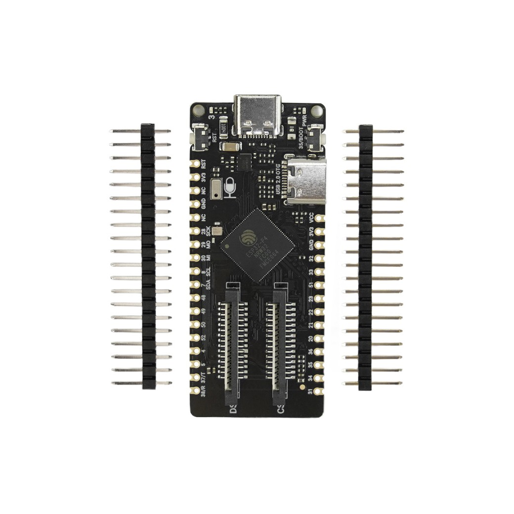
- FireBeetle 2 ESP32-P4 Development Board x1
- 20-pin 2.54mm Male Header x2
PROJECTS
Project 1: [FireBeetle 2 ESP32 P4 Development Kit] Home Assistant IoT Thermometer
Introduction: This article presents the project design of DFRobot FireBeetle 2 ESP32 P4 Development Kit for an IoT remote thermometer, which collects temperature data via ADC and uploads it to the Home Assistant platform through MQTT protocol and WiFi module. It covers development environment setup, hardware connections, project testing, flowcharts, code, MQTTX testing, HA testing, and operational demonstrations.
Project 2: [FireBeetle 2 ESP32 P4 Development Kit] Home Assistant IoT Stepper Motor Control
Introduction: This article presents the project design of DFRobot FireBeetle 2 ESP32 P4 Development Kit for remote stepper motor rotation control via Home Assistant, utilizing WiFi module and MQTT protocol. Includes project introduction, flowchart, hardware connections, flowchart, engineering code, HA dashboard design, and operational demonstrations.
Project 3: Using a Raspberry Pi-Compatible CSI Camera with FireBeetle 2 ESP32 P4 (ESP-IDF)
Introduction: This guide explains how to interface a Raspberry Pi-compatible CSI camera with the FireBeetle 2 ESP32 P4 development board using the ESP-IDF framework.
3. Tutorial - First Time Use
3.1 Arduino IDE Configuration
When you use the ESP32 for the first time, you need to know the following steps:
- Add the ESP32 development board in Arduino IDE (How to add the ESP32 board to Arduino IDE?)
- Select the development board and serial port
- Burn the program
3.2 Select Development Board
- Click Tools->Board, select "ESP32P4 Dev Module".

- The development board needs to be set before burning the code:
- USB CDC On Boot:
- Enabled: Print serial port data through the USB interface
- Disabled: Print serial port data through TX and RX
- Partition Scheme: Disk partitioning scheme. Please select the appropriate storage space according to the Flash of the development board.
- Port: Development board port (Just make sure the COM number is correct, which has nothing to do with the subsequent chip model.)
- USB CDC On Boot:

3.3 LED Blinking
- Copy the code into the window and click "Upload" to upload the code.

- Wait for the burning to complete, and you can see the on-board LED light start to flash.
- If the LED light does not flash, reset the development board.
- If the burning fails, please check Frequently Asked Questions.

วิธีการชำระเงิน
ชำระเงินค่าสินค้าโดยการโอนเงินเข้าบัญชีธนาคาร KBANK, SCB, BBL,TMB
กรุณาเก็บหลักฐานการโอนเงินของท่านไว้เพื่อแจ้งการชำระเงินด้วยค่ะ
ท่านสามารถแจ้งการชำระเงินผ่านระบบอัตโนมัติได้โดย Click Link ข้างล่างค่ะ
https://www.arduitronics.com/informpayment
ชำระเงินผ่านธนาคาร


@rfm0967y
ติดต่อสอบถาม
Join เป็นสมาชิกร้านค้า
MEMBER
