
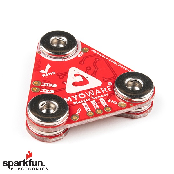
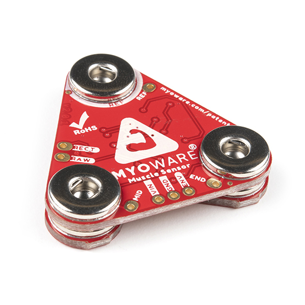
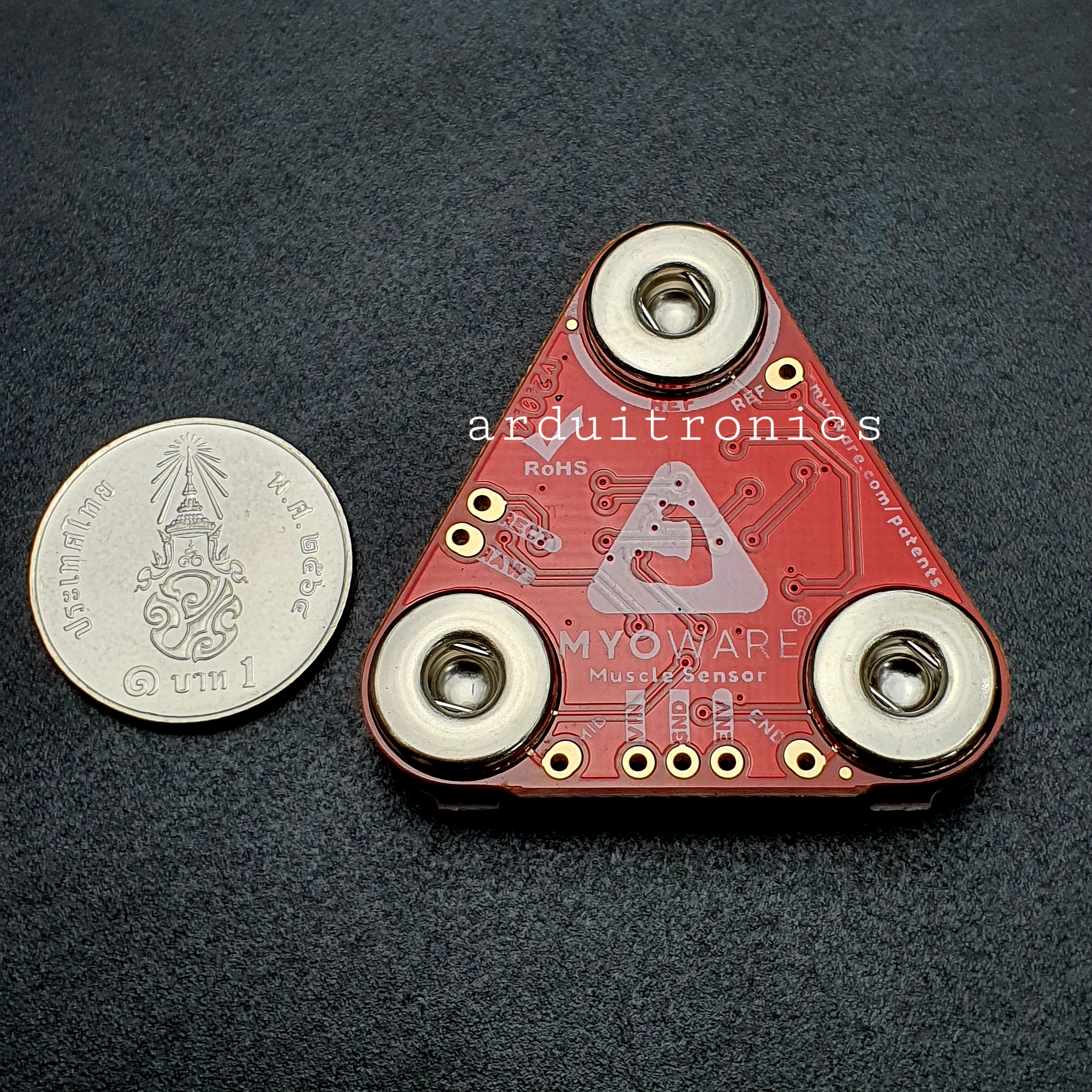
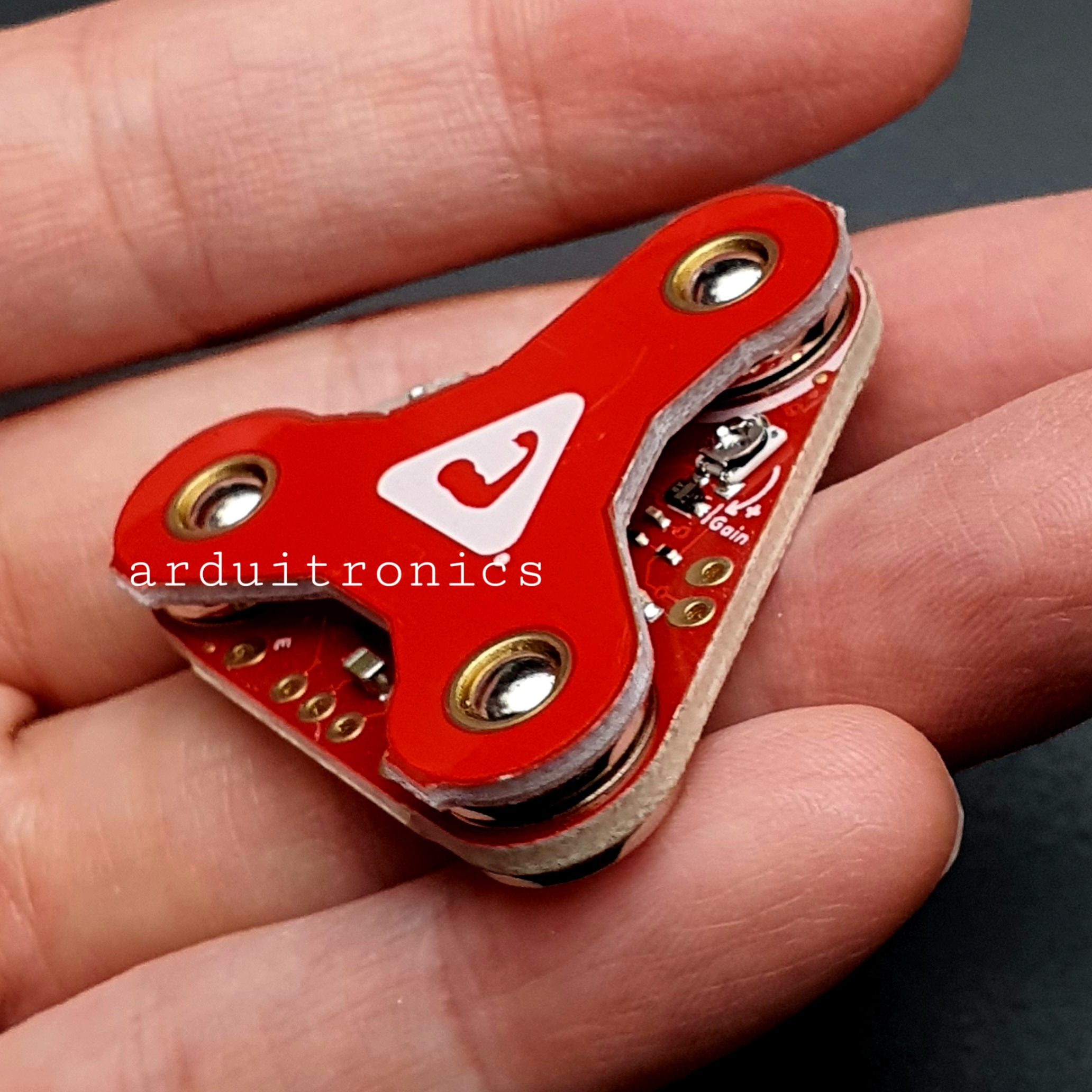
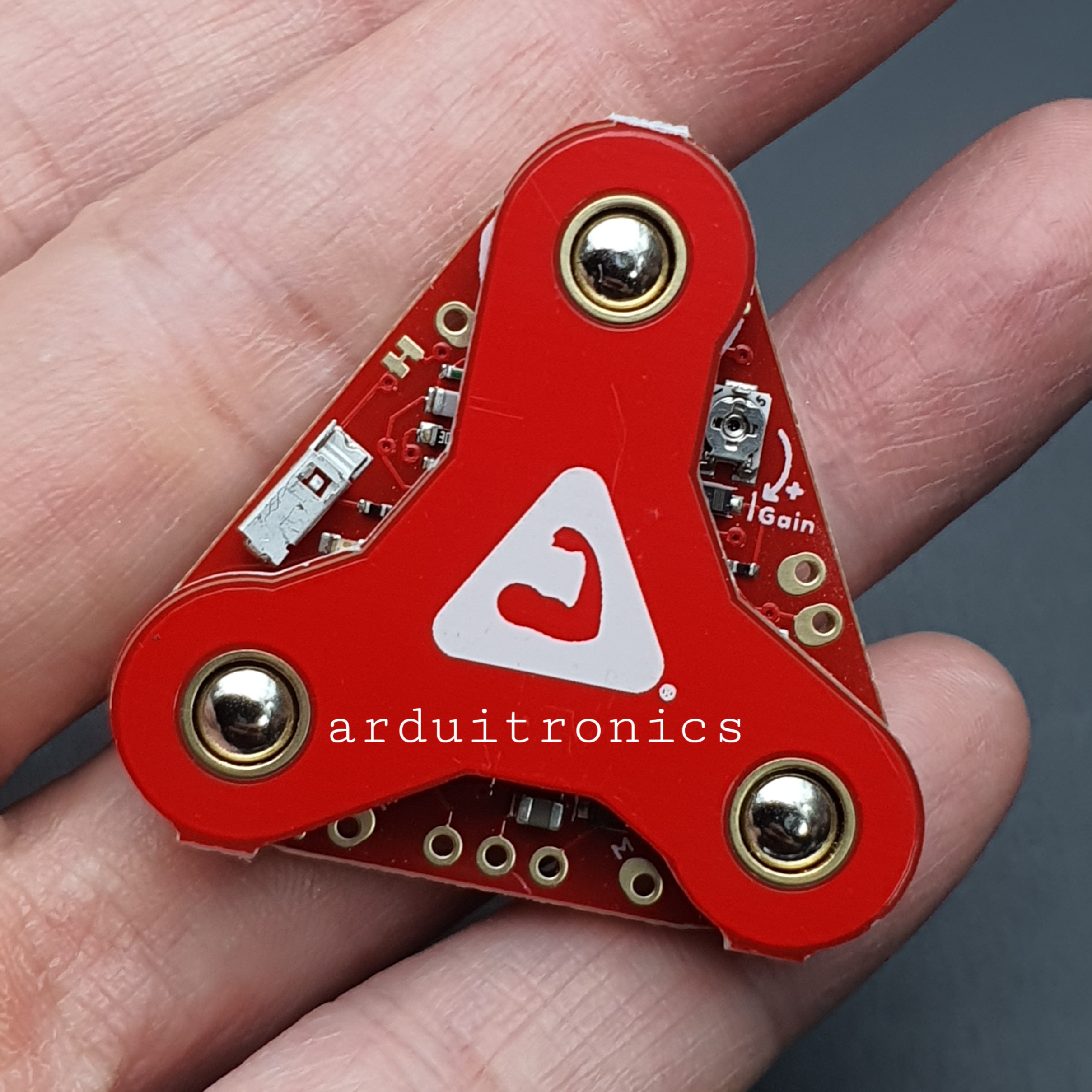
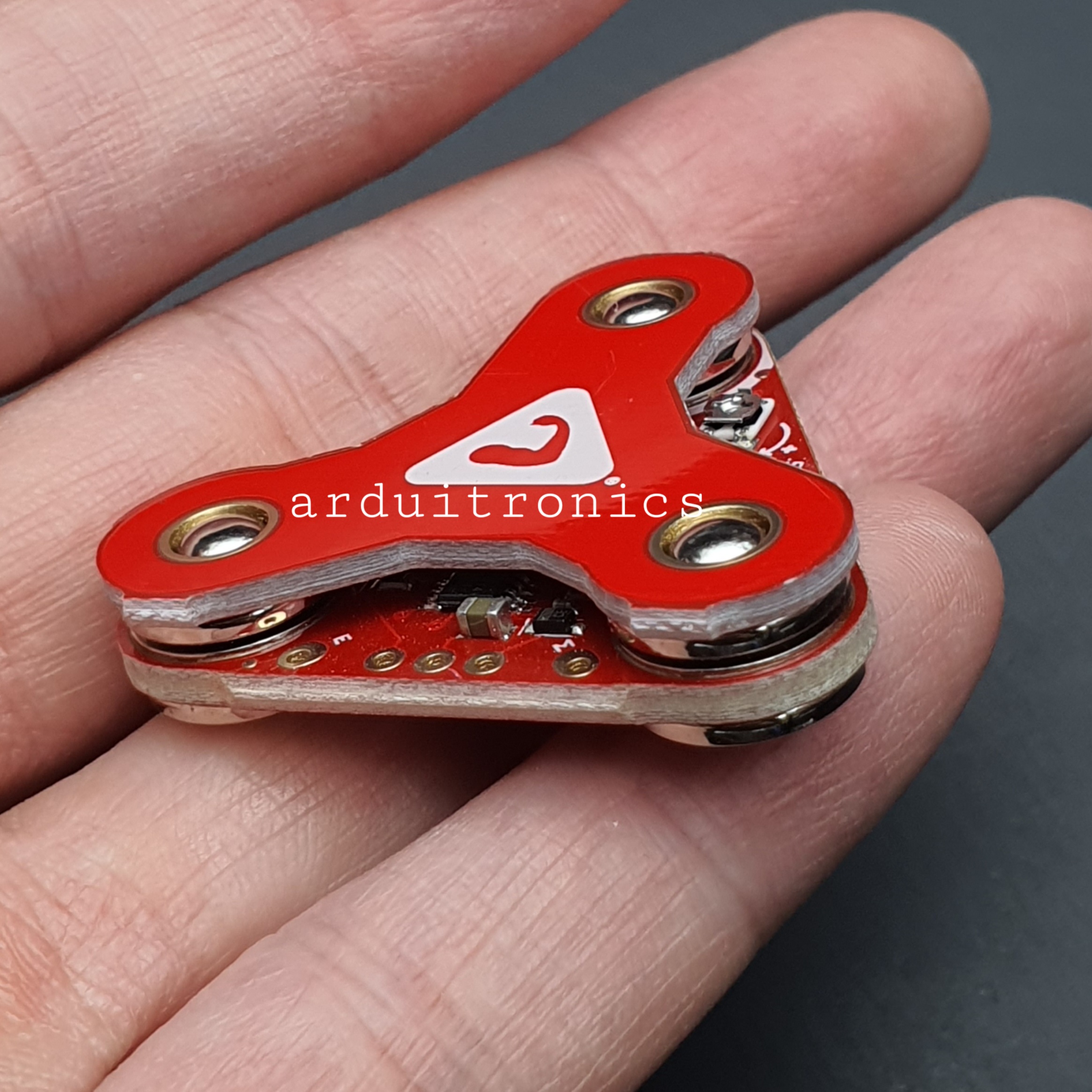
MyoWare 2.0 Muscle Sensor (แท้ Sparkfun, USA) เซ็นเซอร์ตรวจจับกล้ามเนื้อ
| รหัสสินค้า | SG20160 |
| หมวดหมู่ | โมดูลเซ็นเซอร์ทางชีวภาพ Biometrics Sensor |
| ราคา | 2,585.00 บาท |
| สถานะสินค้า | พร้อมส่ง |
| จำนวน | ชิ้น |

รายละเอียดสินค้า
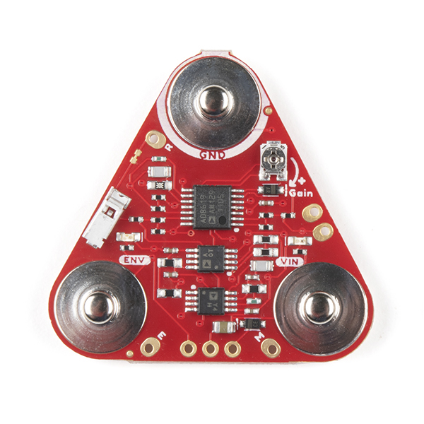
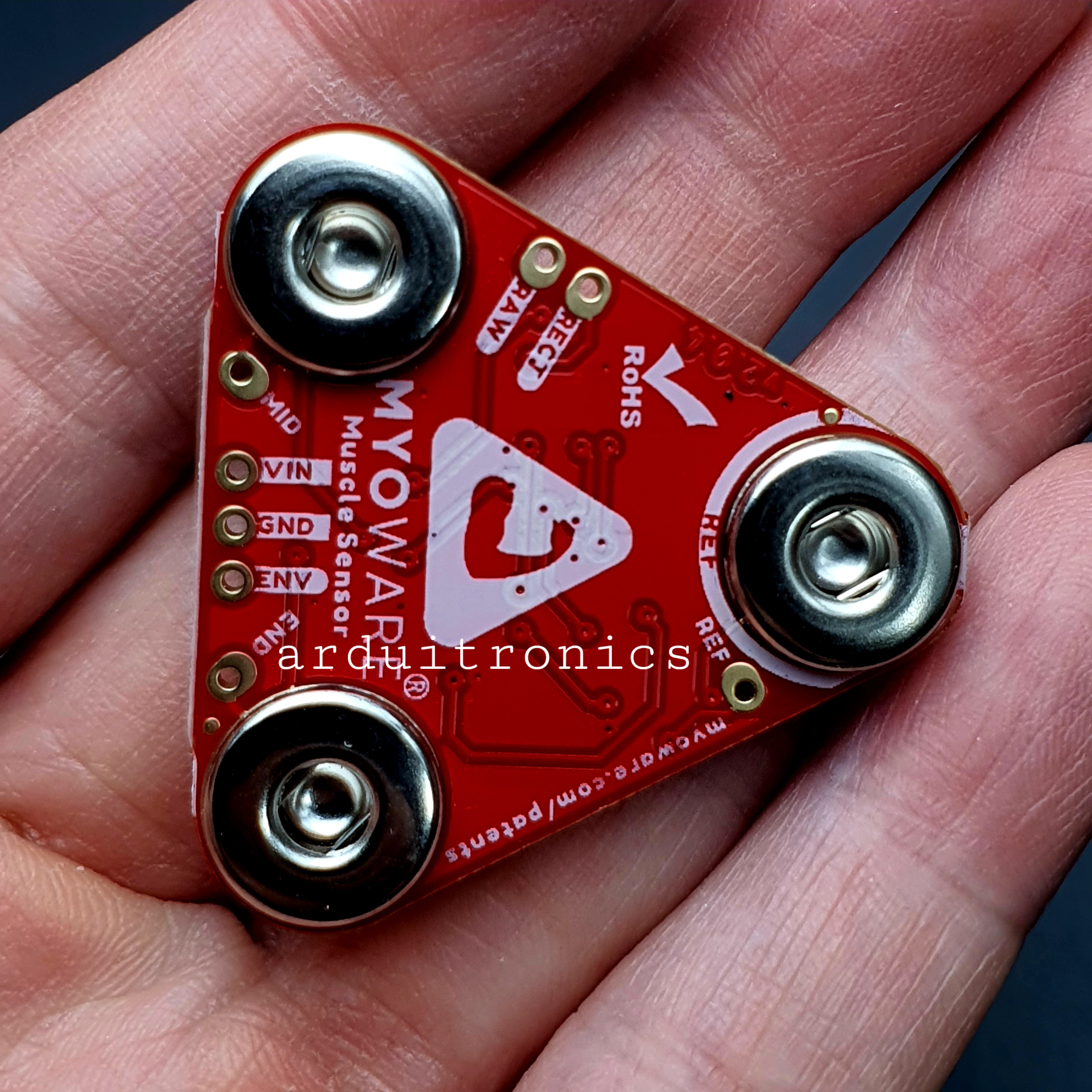
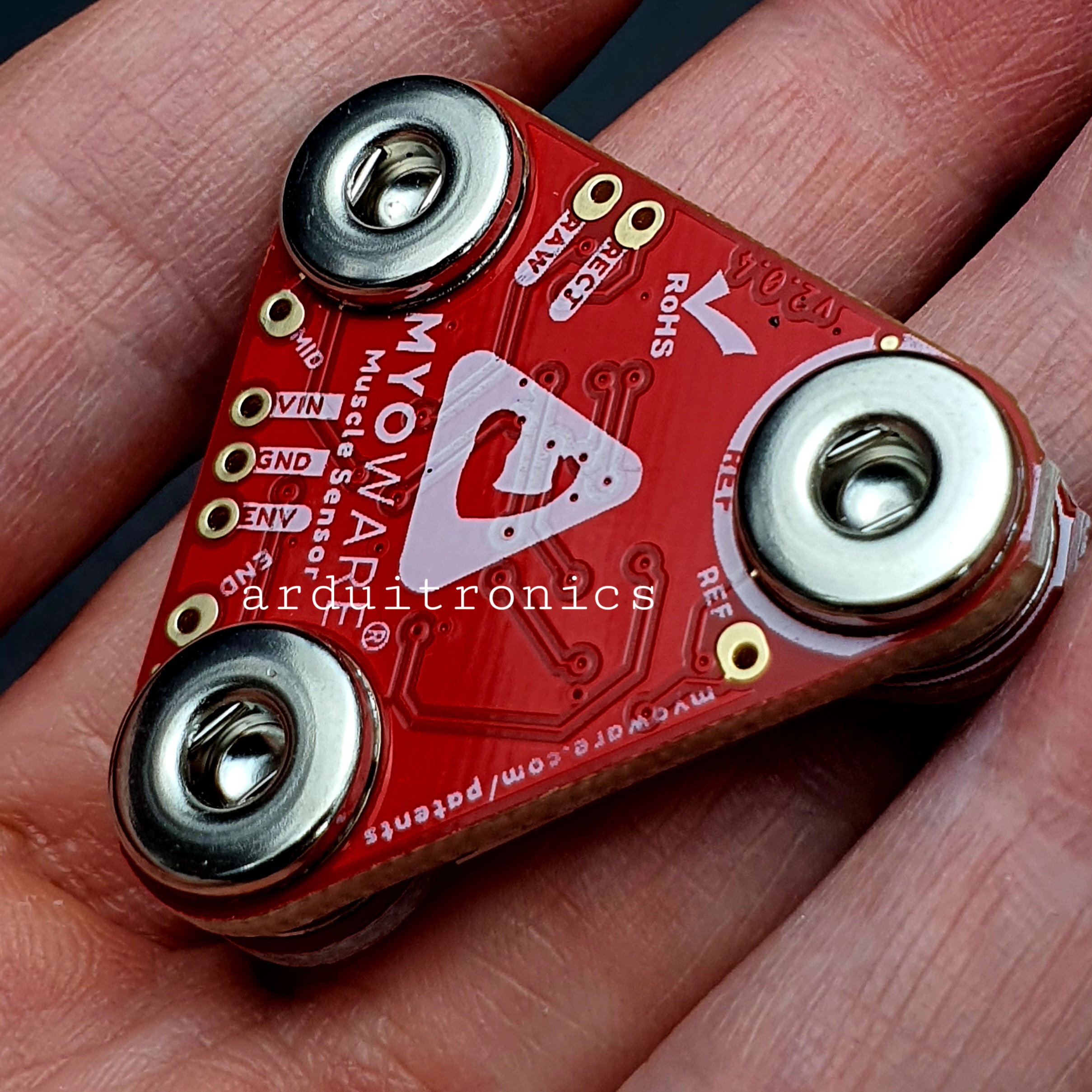
Using our muscles to control things is the way that most of us are accustomed to doing it. We push buttons, pull levers, move joysticks... but what if we could take the buttons, levers and joysticks out of the equation and control it with our muscles? The MyoWare® 2.0 Muscle Sensor is an Arduino-compatible, all-in-one electromyography (EMG) sensor from Advancer Technologies that allows you to do just that! The MyoWare 2.0 Muscle Sensor has been redesigned from the ground up with a new easy-to-use, compact design and upgraded with the latest and greatest chipset improving sensor performance and reliability. The innovative snap connector system eliminates the need to solder connections for the MyoWare 2.0 ecosystem. It's that easy: stick on a few electrodes (not included), read the output voltage and flex some muscles!
Features:
- Wearable Design
- Supply Voltage
- Minimum: +2.27V
- Typically: +3.3V to +5V
- Maximum: +5.47V
- Input Bias Current
- 250pA, max 1nA
- Reverse Polarity Protection
- Three Output Modes
- Raw EMG
- Rectified
- Envelope
- Expandable via Shields
- MyoWare® 2.0 Muscle Sensor Form Factor
- 3x Female Snap Pins (Power and EMG Envelope Output)
- 3x Male Snap Pins (Input Electrodes)
- LED Indicators
- VIN
- ENV
- Reference Electrode Jumper
- Specially Designed For Microcontrollers
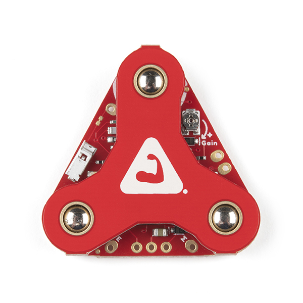
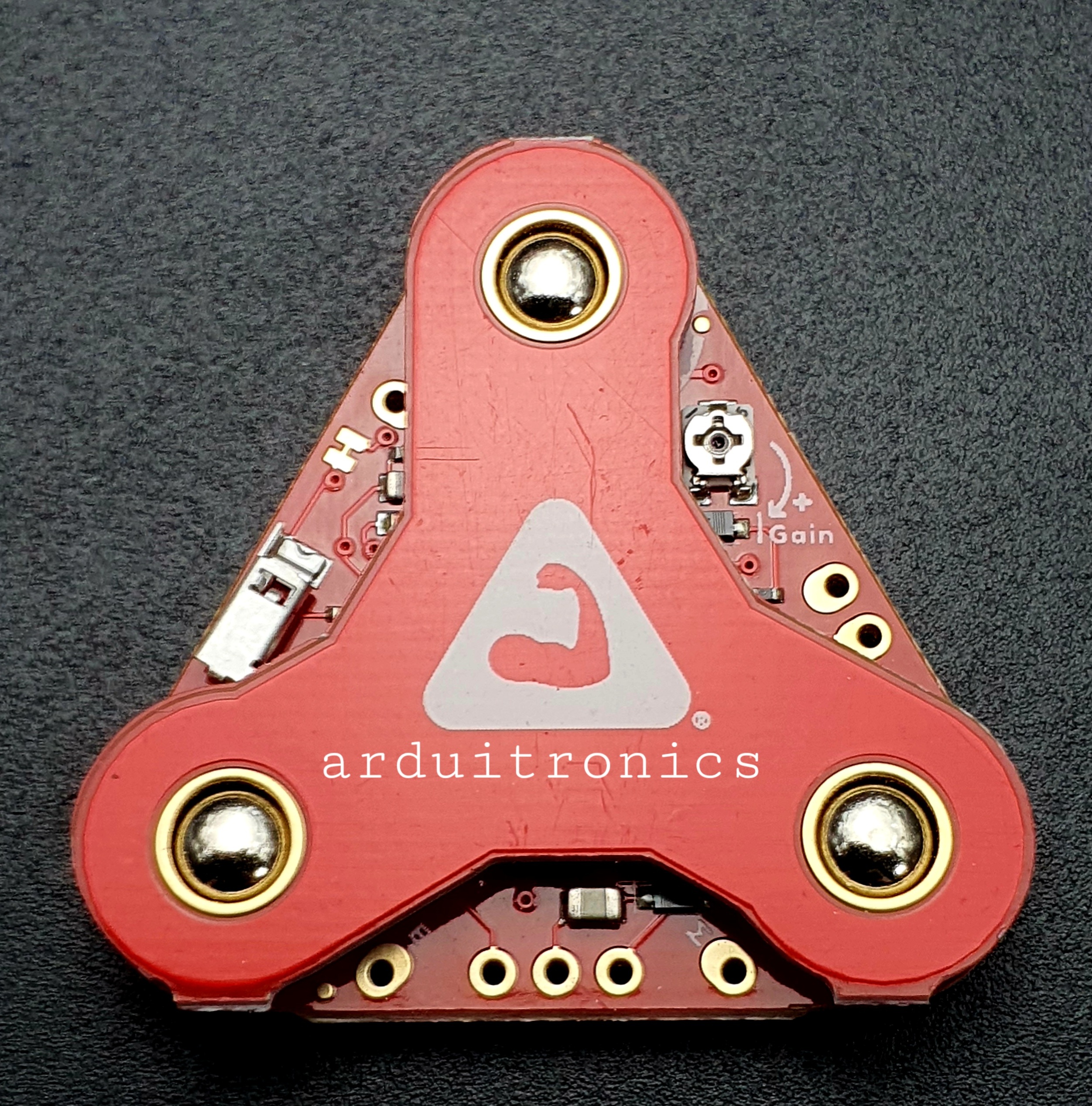
- Adjustable Gain
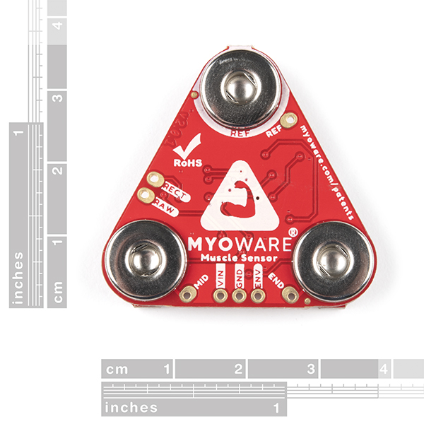
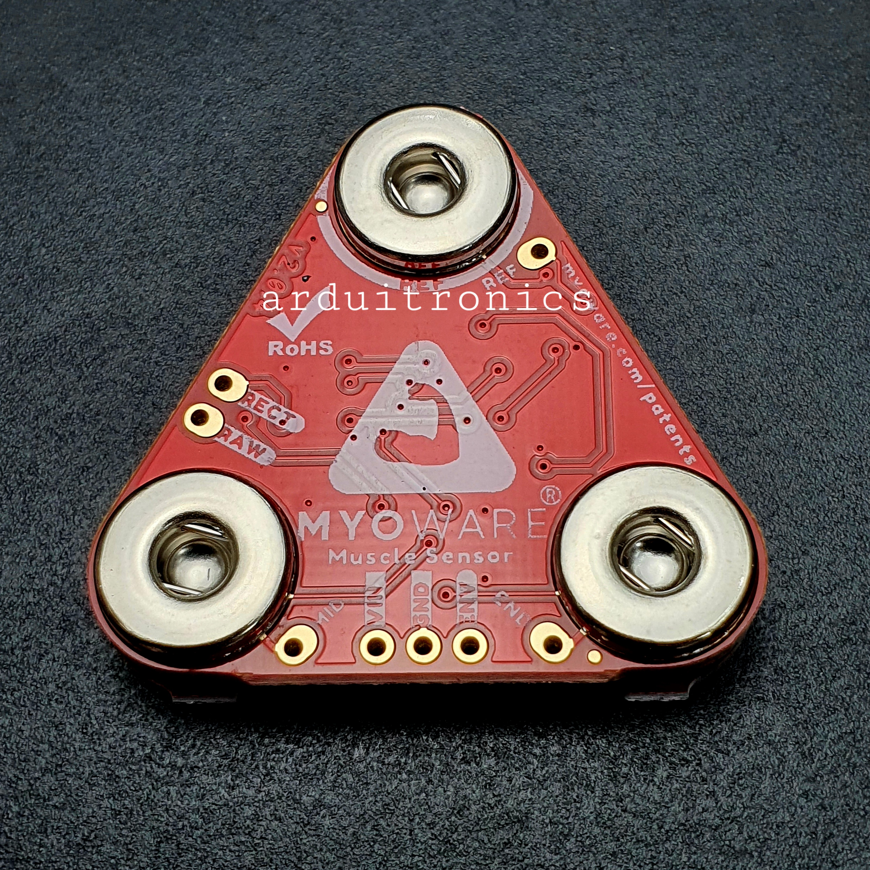
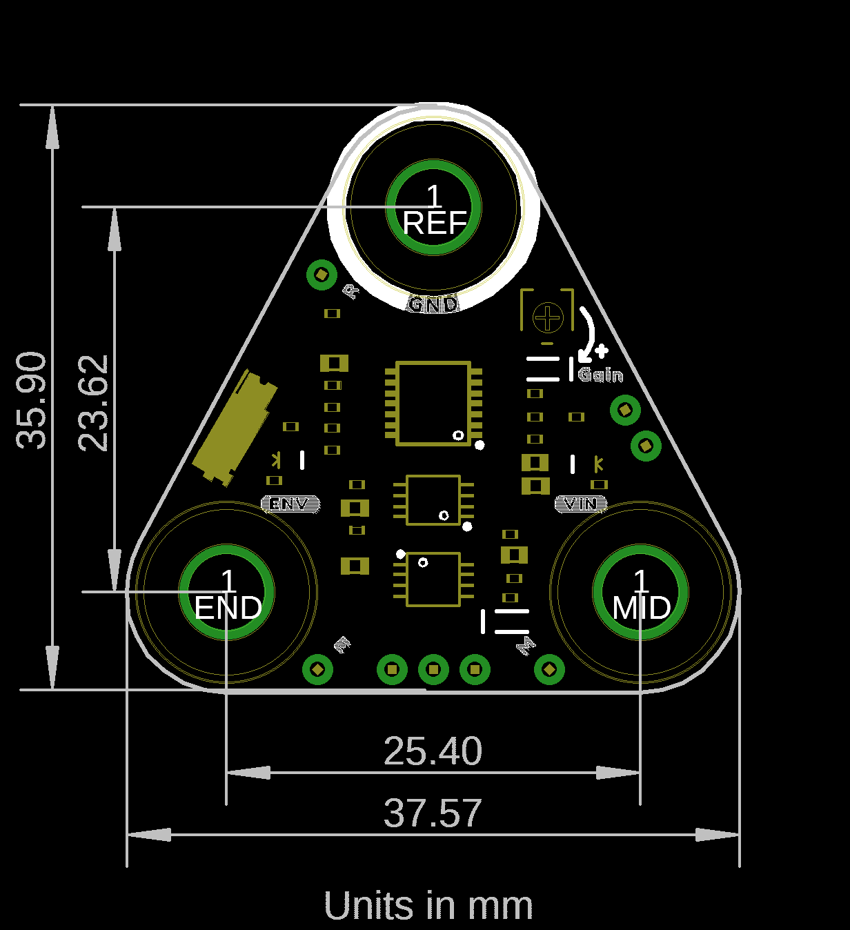
- Board Dimensions
- 37.57mm x 35.90mm (1.48” x 1.41”)
- Board Dimensions
- Hookup Guide
- Advancer Technologies: MyoWare® 2.0
- Quickstart Guide (4.37MB)
- Advanced Guide (9.00MB)
- Patents [1]
- Arduino Reference Language: ArduinoBLE Library
- GitHub Example Repo
- MyoWare 2.0 Ecosystem Page
Hardware Hookup
Advancer Technologies has provided a Quick Start and Advanced Guide for the MyoWare 2.0 Muscle Sensor. Feel free to check them out with this guide.
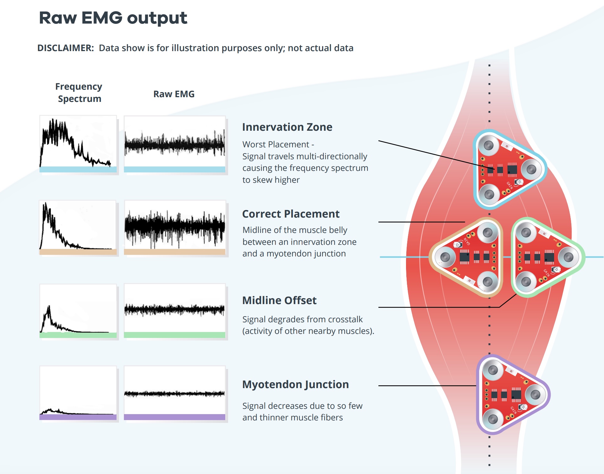
Selecting a Muscle Group
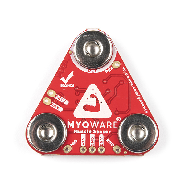
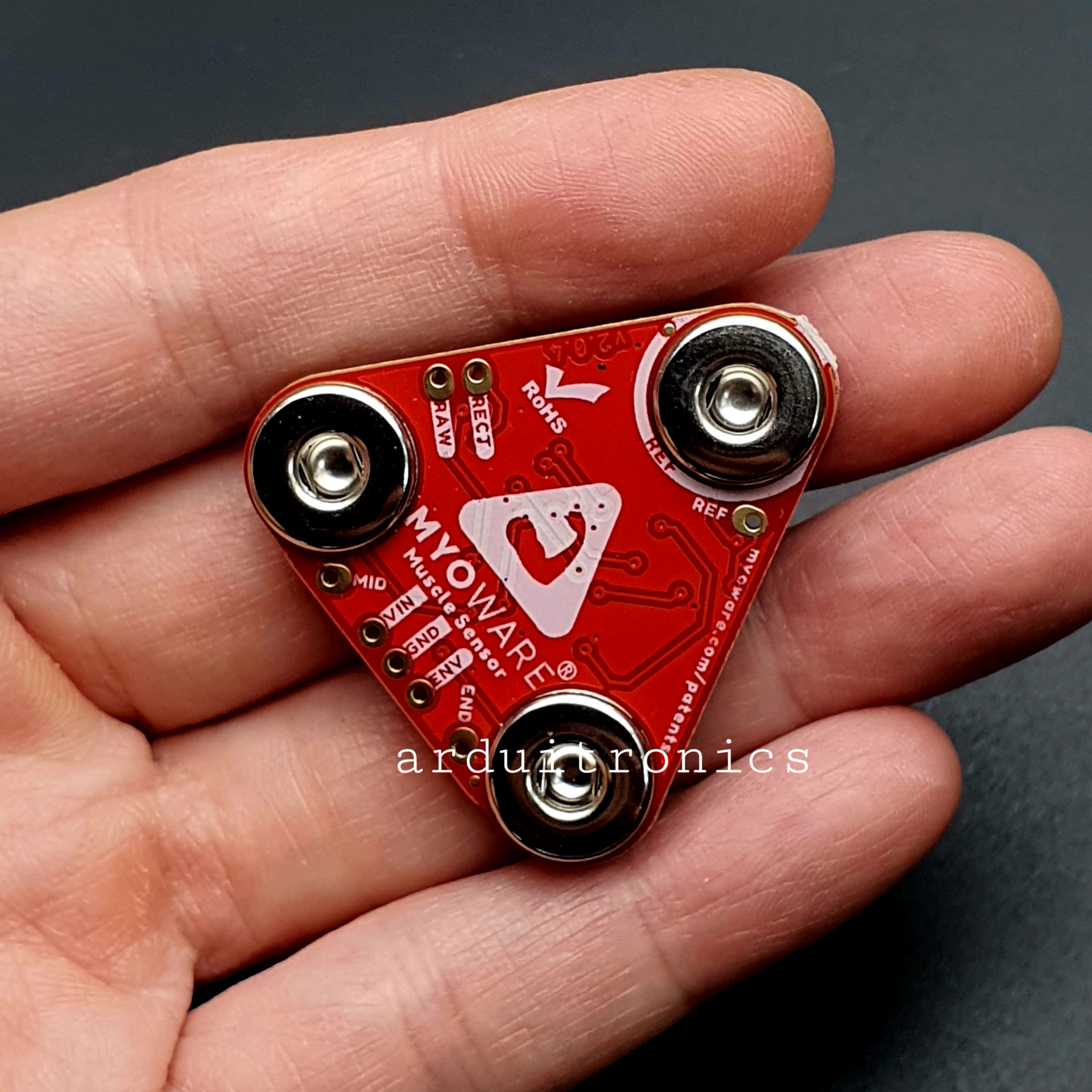
Select a muscle group to place the MyoWare 2.0 Muscle Sensor. Placement of the sensor is critical when measuring the muscle activity. You will need to connect the MID electrode to the middle of the muscle body with the END electrode lined up in the direction of the muscle length. The REF electrode will be adjacent to the muscle body.
We'll be using the forearm as an example. You can connect the sensor to any muscle group as long as orient the sensor's electrodes with respect to the target muscle as explained above. Note that the muscle group shown in the image below are not to scale.
For more other muscle groups, check out the MyoWare 2.0 Advanced Guide. Make sure to zoom in on the image for a closer look at the muscle group. The positions shown in the image are approximate.

Preparing the Skin
Grab an alcohol swab to clean the skin where the MyoWare 2.0 Muscle Sensor will be placed. Cleaning the skin with soap can leave a residue on the skin and should be avoided.

Clean the skin where the EMG pads will stick using an alcohol swab. A cotton ball soaked in isopropyl alcohol is also sufficient to remove any oils or surface contaminants on the skin. Allow the isopropyl alcohol to evaporate before sticking the EMG pads on the skin
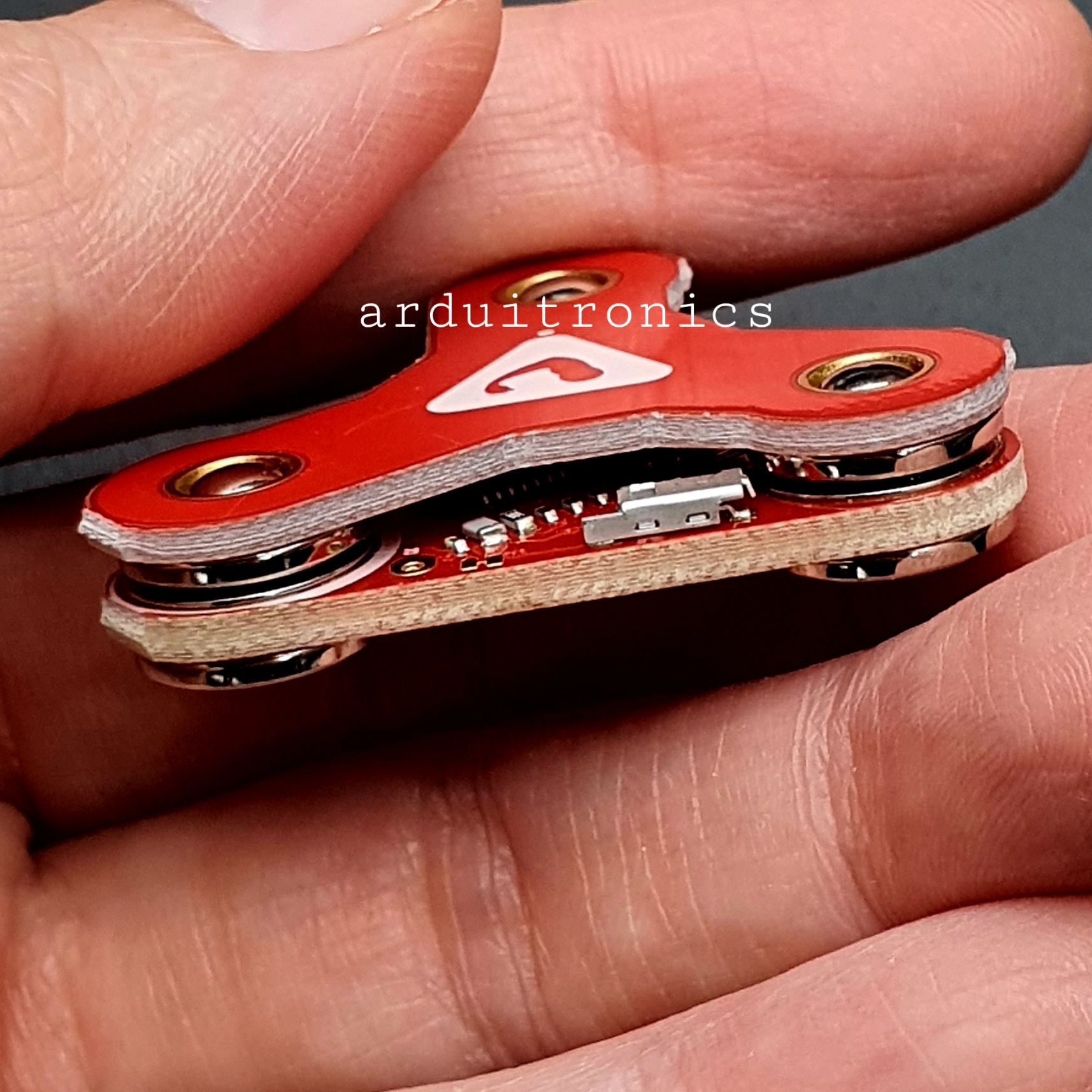
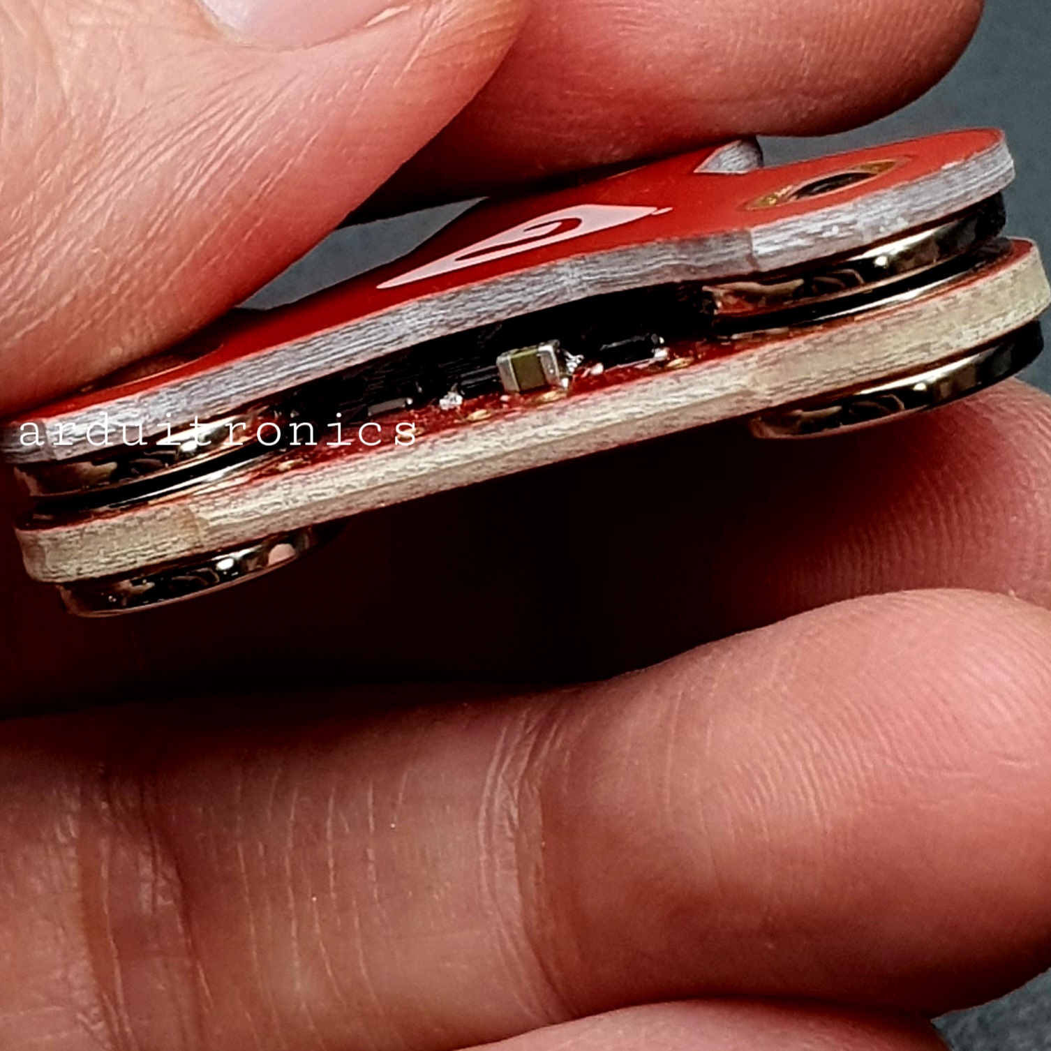
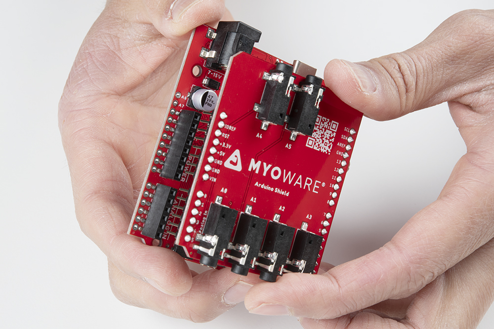
Stacking Shields
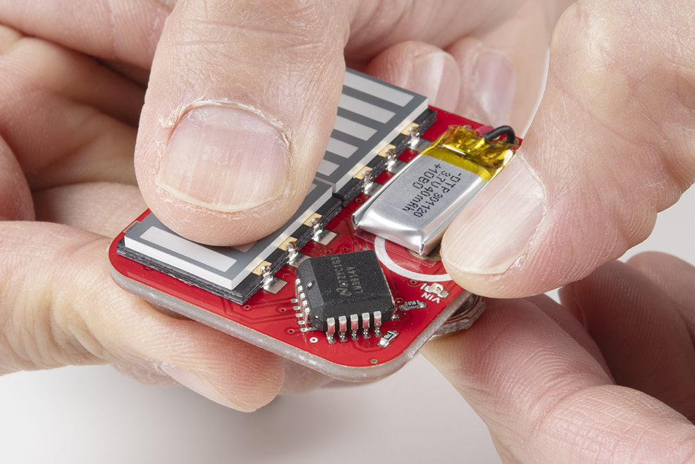
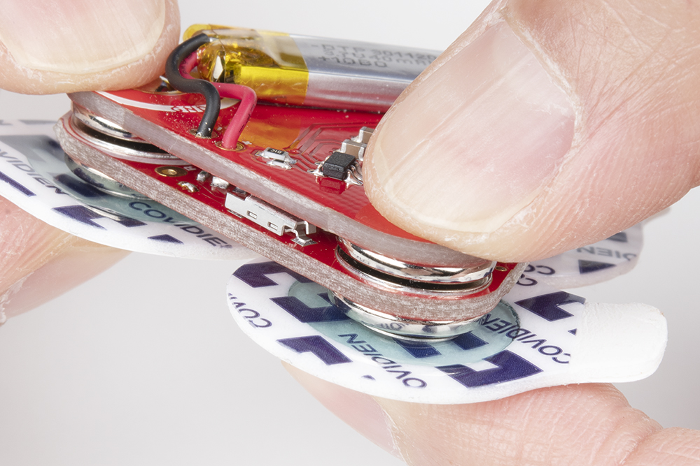
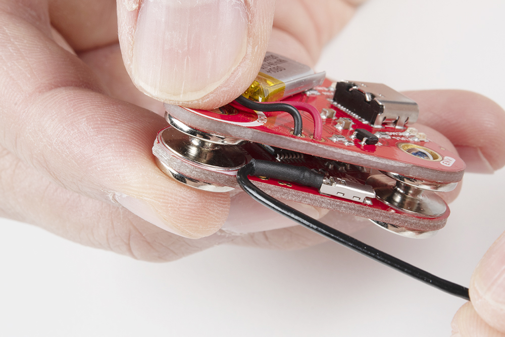
Since the shields are keyed, there's only one way to stack the boards together! Just look for the snap connector labeled as GND or REF. Align the snap connectors. Make sure the power switch is flipped to the OFF position for shields.
Push down on the snap connectors using your thumb and index finger. Make sure to avoid pressing down on the built-in LiPo battery.
 |
 |
Connecting to a Muscle Group
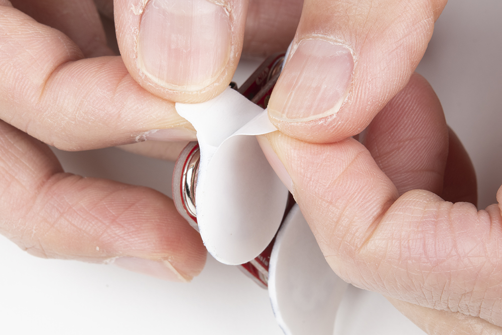
Snap the EMG pads to the bottom of the MyoWare 2.0 Muscle Sensor. For users using the MyoWare 2.0 Cable Shield, you'll be snapping it to the sensor cable's snap connectors.
Peel and carefully remove the backs of the electrodes to expose the adhesive.
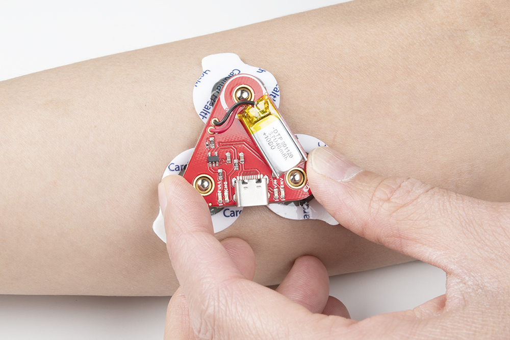
Attach the pads to the target muscle. In this case, we are using our right forearm.
Ensure that power is disconnected when stacking shields on the top side of the MyoWare 2.0 Muscle Sensor. Once everything is connected, flip the power switch to the ON position on the Power Shield or LED Shield. For users connecting the sensor to an Arduino and computer, check to make sure that your computer is not connected to the wall outlet. Then flip the power switch to the ON position on the Link Shield.
Connecting Shields to Arduino
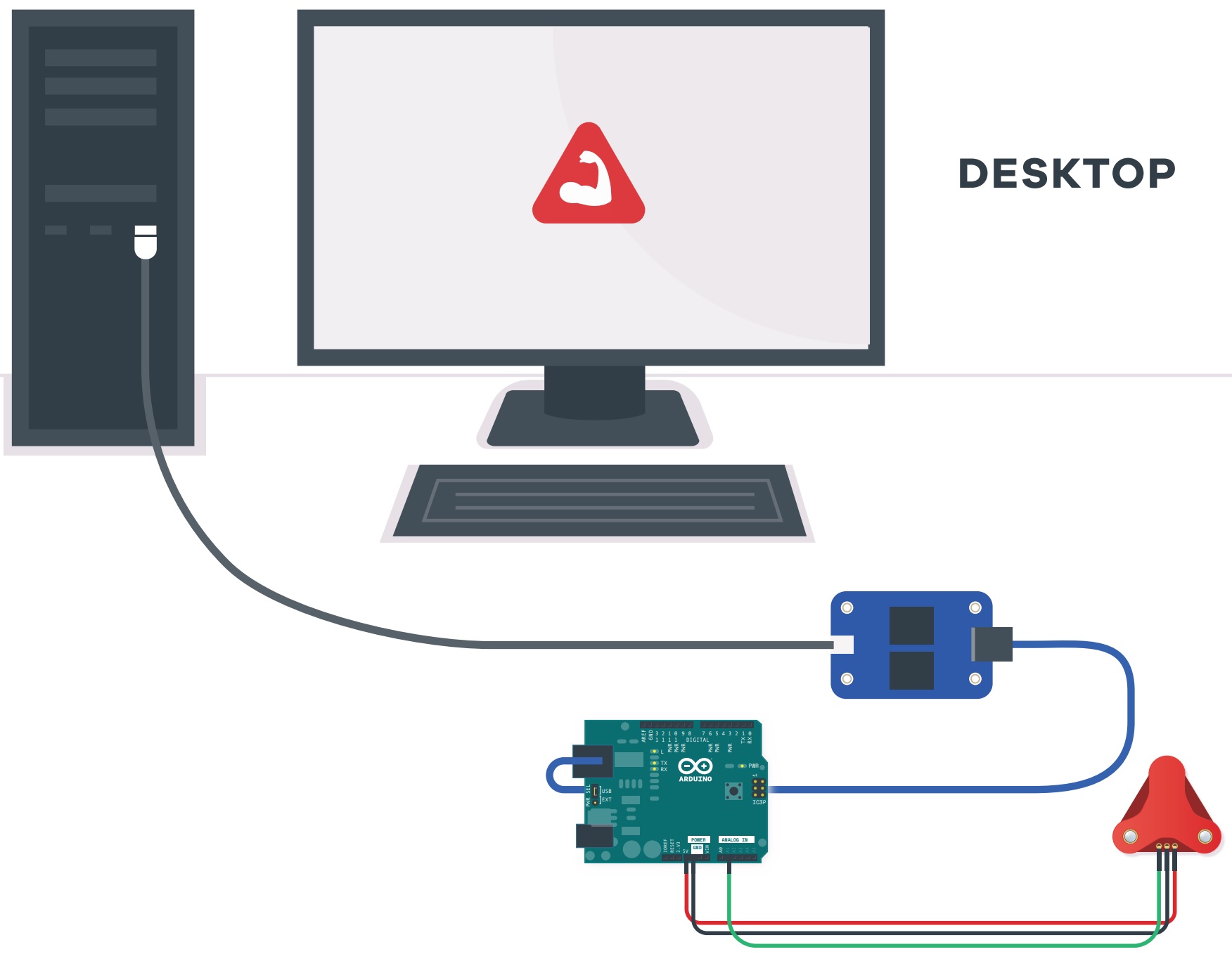
Image Courtesy of Advancer Technologies taken from the MyoWare 2.0 Quick Start Guide
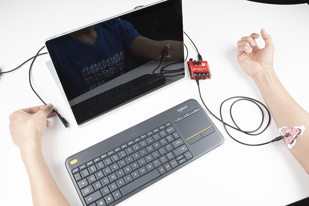
If you do not have a USB isolator, try using a laptop running on battery power and ensure that you are not connecting the laptop to a wall outlet.

Image Courtesy of Advancer Technologies taken from the MyoWare 2.0 Quick Start Guide
We also recommend using a wireless keyboard and mouse when programming in Arduino. The muscle sensor is sensitive enough that it can also pick up a signal from the trackpad or keyboard on your laptop when running on power. As a result, the muscle sensor will have false readings and the Arduino's analog pin will read high.
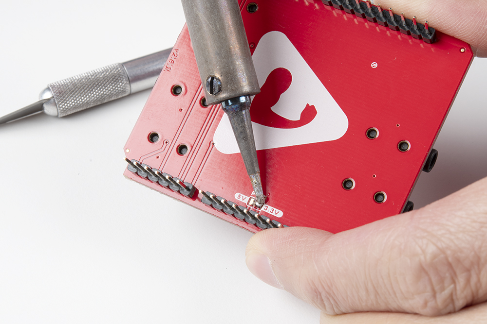
For users using a 3.3V Arduino, we recommend adjusting the PWR jumper by cutting the default trace and adding a solder jumper between the center pad and the 3.3V side. For users using a 5V Arduino, you can leave the jumper connected to the 5V side. For more information on modifying the jumpers, check out our tutorial on working with jumper pads and PCB traces.
Stack the Arduino Shield on your chosen development board with the Arduino Uno R3 footprint.
Insert the TRS cable between the MyoWare 2.0 Link Shield and Arduino Shield's TRS connector. In this case, we will be using the connector labeled as A0. Make sure to adjust the code when using the other channels.
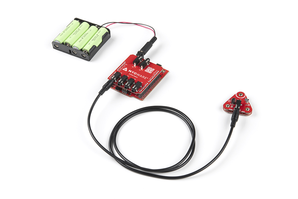
For remote applications, we recommend using a battery pack. In this case, we used AA batteries (NiMH) and a 4xAA battery pack to power the system.
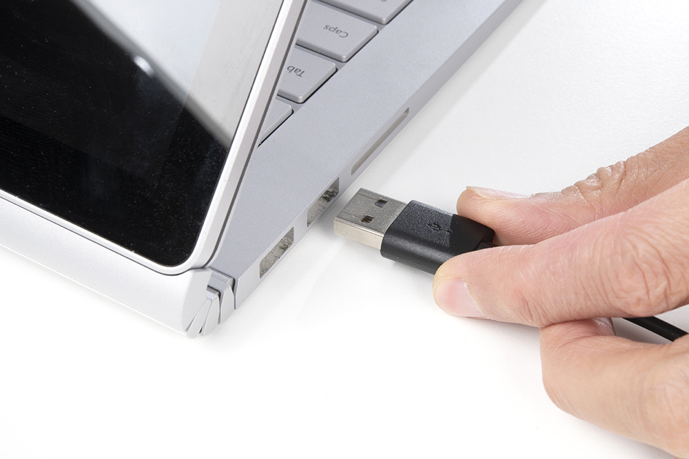
Make sure to remove the power supply from your computer before connecting your Arduino with the MyoWare 2.0 Muscle Sensor to your USB port. This is to prevent noise and safeguard against electrical shock when connected to the power grid. This includes any computer docks and external monitors.
When ready, insert the USB cable between your Arduino and computer's USB port.
For users transmitting sensor data via Bluetooth, attach a battery pack to the RedBoard Artemis acting as the Bluetooth peripheral device. This is assuming that it has the Bluetooth peripheral example code uploaded. Connect the RedBoard Artemis acting as the Bluetooth central device to your computer's USB port. Since the Bluetooth peripheral device is disconnected, you could connect your laptop to a power supply since the MyoWare 2.0 Muscle Sensor is not connected to the main outlet. You just need to make sure to unplug the power supply every time you need to reprogram the RedBoard Artemis acting as the peripheral device.
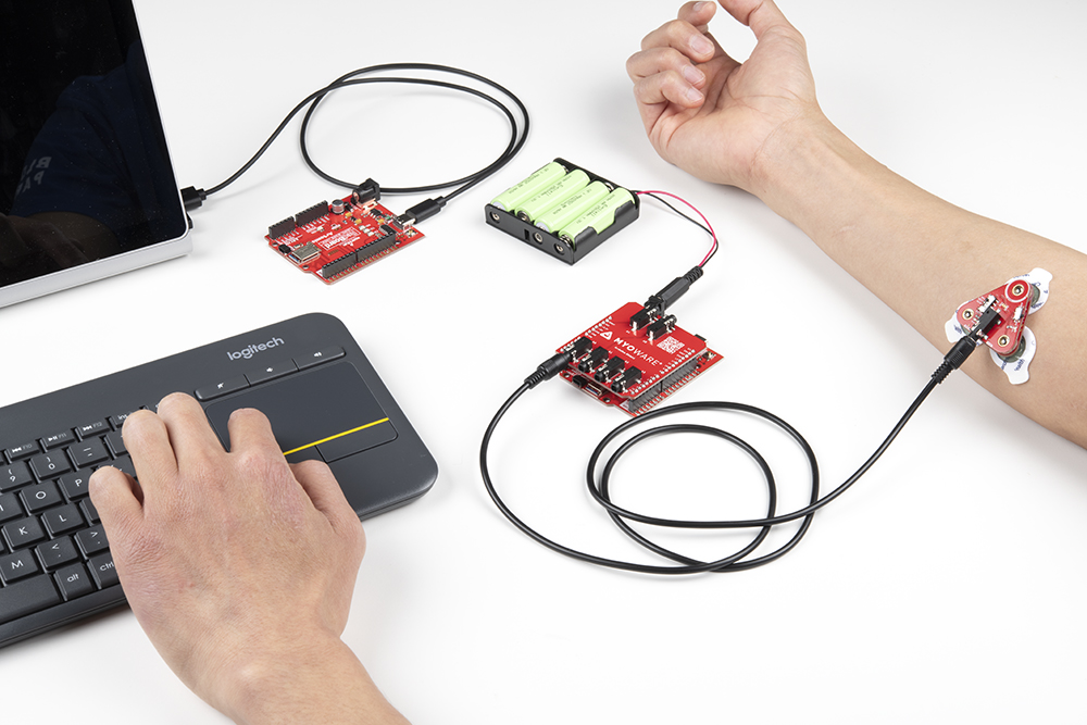
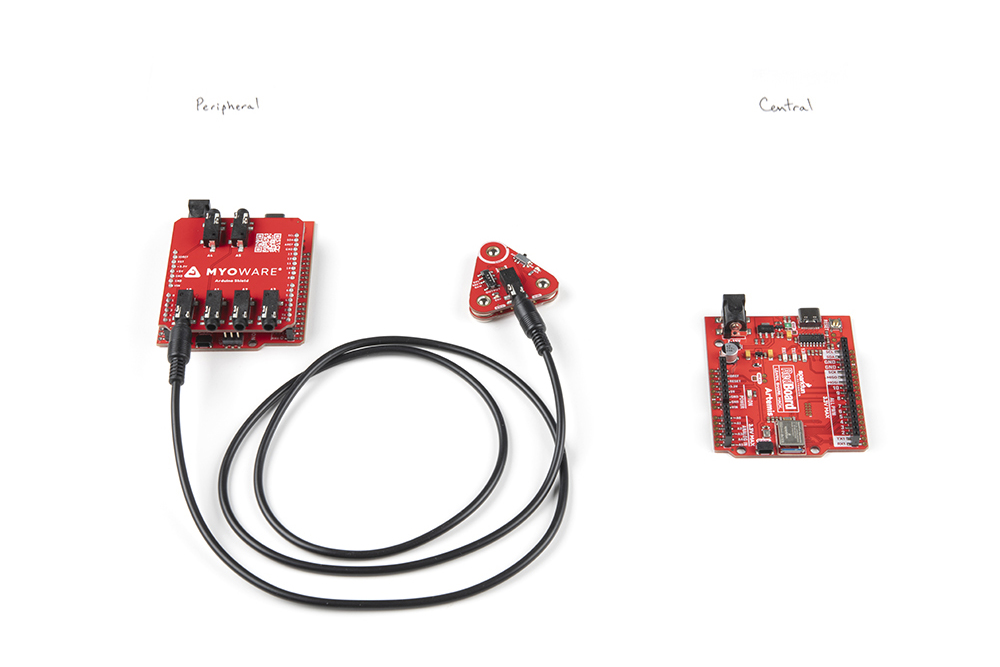
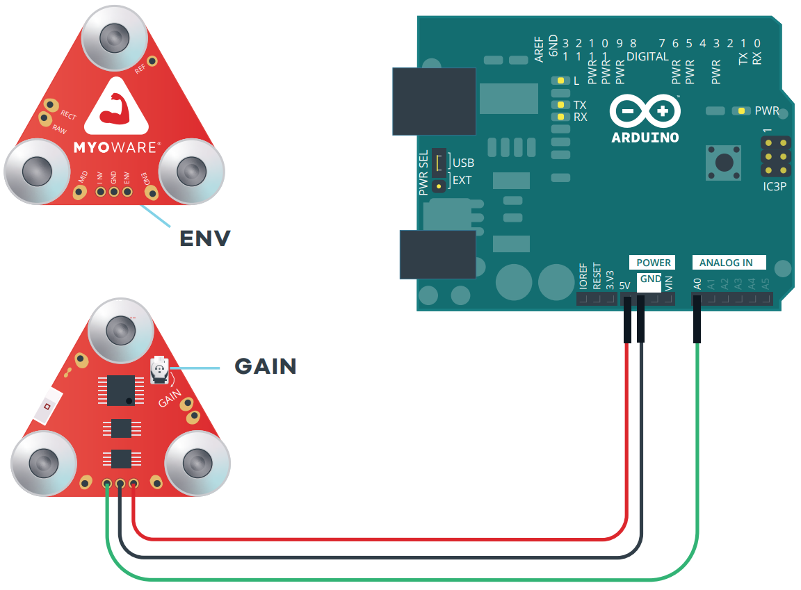
Image Courtesy of Advancer Technologies taken from the MyoWare 2.0 Advanced Guide
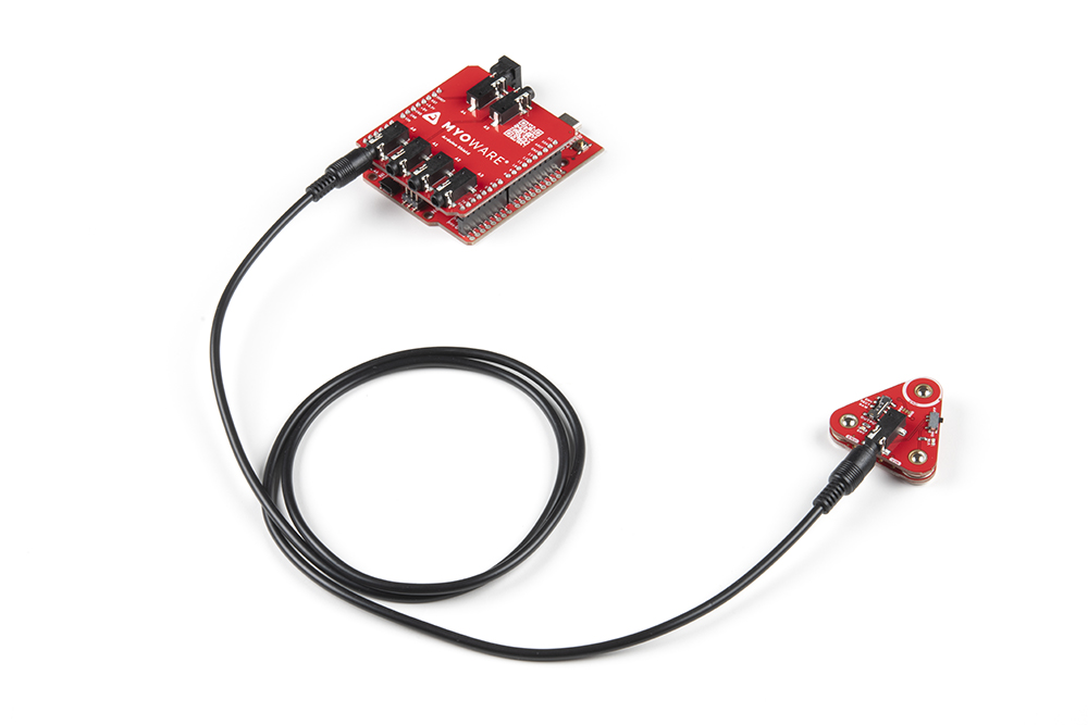
External Cable
For muscles that require you to mount the sensor pads away from the sensor, snap the MyoWare 2.0 Cable Shield on the bottom of the MyoWare 2.0 Muscle Sensor. Then insert the sensor cable into the 3.5mm TRS connector.
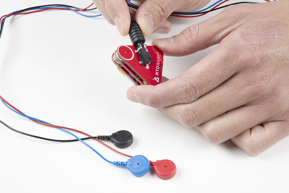
Attach the EMG pads to the snap connectors. After cleaning the skin and selecting the muscle, peel and remove the backs of the electrodes to expose the adhesive. Then attach the pads to the target muscle group based on the MID, END, and REF.
| Snap Connector | TRS Pin | Electrode Pin [CAB-12970] |
|---|---|---|
| Reference [REF] | Sleeve | Black |
| End [END] | Ring | Blue |
| Middle [MID] | Tip | Red |
Reference Cable
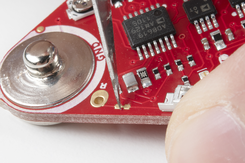
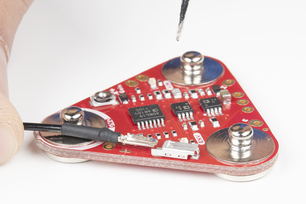
With a hobby knife, slice the reference jumper pad closest to the GND pin. There are traces near the jumper so you will need to make sure to avoid cutting traces that are adjacent to jumper pad. For more information on modifying the jumpers, check out our tutorial on working with jumper pads and PCB traces.
Then insert the reference cable into the MyoWare 2.0 Muscle Sensor, slide the pin into the housing with the tab facing away from the board.
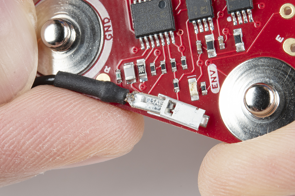
When stacking a shield on top of the MyoWare 2.0 Muscle Sensor, make sure carefully pull the cable away from the shield's snap pin.
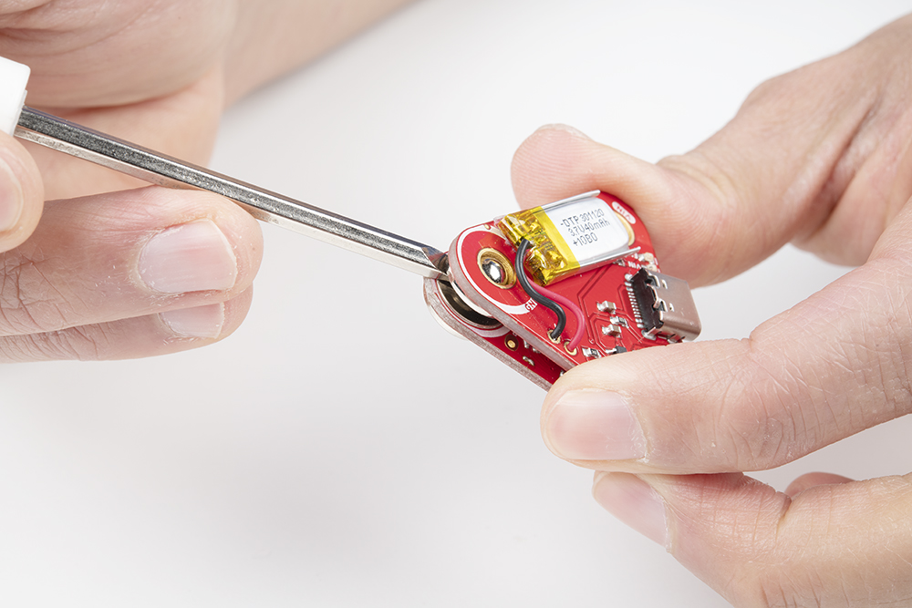
To remove the reference cable, push the tab into the housing with the end of a flathead screwdriver and gently pull the pin out of the housing.
 |
 |
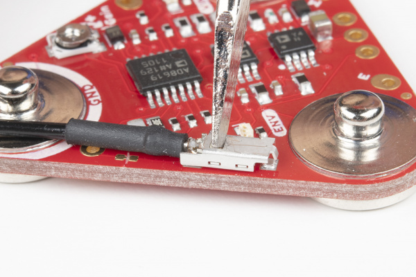
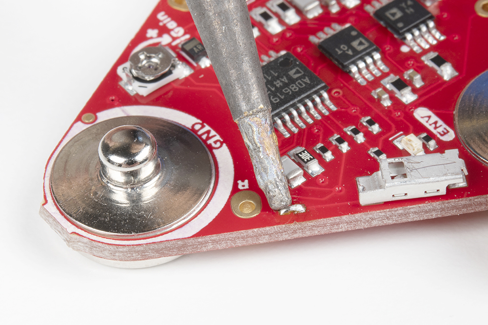
To close the jumper pad, add a small amount of solder on the jumper pad.
Disconnecting the MyoWare Shield
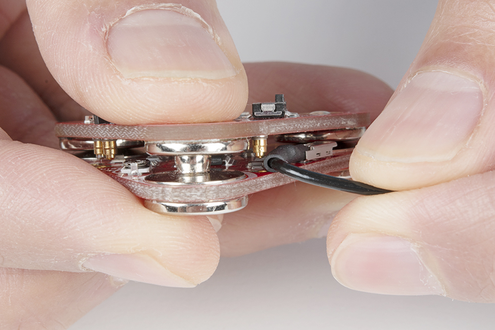
When prototyping, you will want to test out different shields or you may need to adjust the trim pot. To remove the boards, you will need a flathead screwdriver. With power off, insert the flathead between the snap connectors and ensure that there are no components in the way of the flathead. Gently slide the flathead between the snap connectors.
Angle the flathead against the connectors until the boards disconnect.

With one side disconnected, pull the boards away from each other so that the other two snap connectors disconnect.
Standalone Example 0: LED(s)
To test the MyoWare 2.0 Muscle Sensor without an Arduino, you could use the MyoWare 2.0 Power Shield or the LED Shield. Both shields have a built-in battery removing the need to solder a power source to the sensor. After stacking the boards together and sticking it to a muscle group, flip the power switch to the ON position. Start flexing the muscle to see if you can light up the ENV LED on the Power Shield or the LED segments on the LED Shield!
If you are using the MyoWare 2.0 Power Shield, observe the ENV LED. The LED will be off. As you flex, the voltage from the ENV pin increases. As a result, the ENV LED will start to light up and increase in intensity as you flex the muscle. If you look closely between the stacked boards, you will also notice the ENV LED on the MyoWare 2.0 Muscle Sensor light up.
If you are using the MyoWare 2.0 LED Shield, observe the LED segments. The LED segments will be off. As you flex, the voltage from the ENV pin increases. As a result, the LED segments will start to light up. The more you flex the muscle, the more LED segments will light up. When fully flexed, all 10x LED segments will be on.

For users that cut the jumper labeled as MODE (i.e. enabling dot mode) on the MyoWare 2.0 LED Shield, you will see a different effect. A leading LED bar (i.e. "dot") will light up and traverse the segments. Any trailing LEDs behind it will be turned off instead of filling in with light. When fully flexed, one LED segment should be on.
Arduino Example 1: Analog Read - Single Sensor
Image Courtesy of Advancer Technologies taken from the MyoWare 2.0 Quick Start Guide
If you do not have a USB isolator, try using a laptop running on battery power and ensure that you are not connecting the laptop to a wall outlet.
Image Courtesy of Advancer Technologies taken from the MyoWare 2.0 Quick Start Guide
We also recommend using a wireless keyboard and mouse when programming in Arduino. The muscle sensor is sensitive enough that it can also pick up a signal from the trackpad or keyboard on your laptop when running on power. As a result, the muscle sensor will have false readings and the Arduino's analog pin will read high.
Example 1: Analog Read - Single
The following example uses an analog input on the RedBoard Plus with an Atmega328P to read the muscle sensor's analog signal. However, you could also use any microcontroller with the Arduino Uno R3 footprint.
If you have not already, select your Board (in this case the Arduino Uno), and associated COM port. Upload the code to the board.
/*
MyoWare Example_01_analogRead_SINGLE
SparkFun Electronics
Pete Lewis
3/24/2022
License: This code is public domain but you buy me a beverage if you use this and we meet someday.
This code was adapted from the MyoWare analogReadValue.ino example found here:
https://github.com/AdvancerTechnologies/MyoWare_MuscleSensor
This example streams the data from a single MyoWare sensor attached to ADC A0.
Graphical representation is available using Serial Plotter (Tools > Serial Plotter menu).
*Only run on a laptop using its battery. Do not plug in laptop charger/dock/monitor.
*Do not touch your laptop trackpad or keyboard while the MyoWare sensor is powered.
Hardware:
SparkFun RedBoard Artemis (or Arduino of choice)
USB from Artemis to Computer.
Output from sensor connected to your Arduino pin A0
This example code is in the public domain.
*/
void setup()
{
Serial.begin(115200);
while (!Serial); // optionally wait for serial terminal to open
Serial.println("MyoWare Example_01_analogRead_SINGLE");
}
void loop()
{
int sensorValue = analogRead(A0); // read the input on analog pin A0
Serial.println(sensorValue); // print out the value you read
delay(50); // to avoid overloading the serial terminal
}
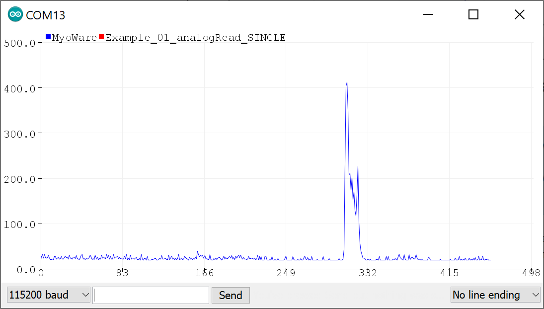
Once uploaded, open the Arduino Serial Plotter (Tools > Serial Plotter) to 115200 baud. Flip the power switch on the MyoWare 2.0 Link Shield to provide power and start flexing! You should see something similar to the output below with the envelope signal. In this case, the MyoWare 2.0 Muscle Sensor was attached to my right forearm. For those that are interested in viewing the serial output, you can also open the Arduino Serial Monitor to see the values.
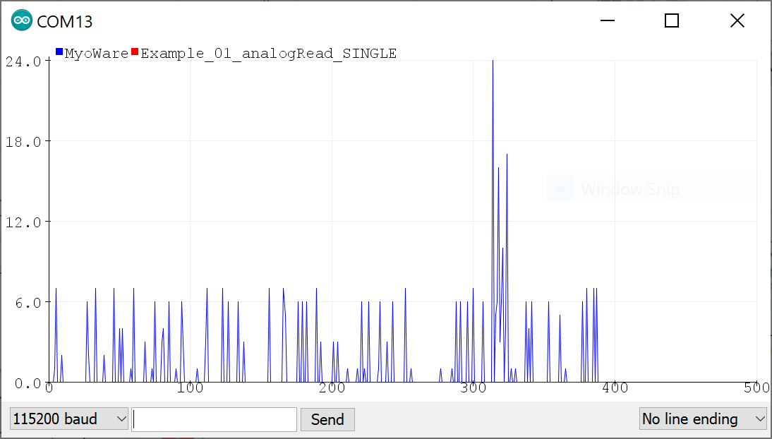
To view the Rectified or Raw signals, flip the power switch to the OFF position on the Link Shield, adjust the OUTPUT switch to either the Rectified or Raw position and then turn the power switch to the ON position. Reopen the Serial Plotter and you will see a smaller signal output when flexing your forearm.
The images below show the forearm being flexed at around 300ms when the signal increases by a value of about 22 for the rectified output and about 20 for the raw output. Note that the raw signal will be centered around a voltage offset of about +VIN/2. Make sure that the +VIN is the maximum voltage of your microcontroller's ADC to ensure that you can see the positive and negative portions of the waveform. The output shown in the graphs are values and have not been converted to voltages.
 |
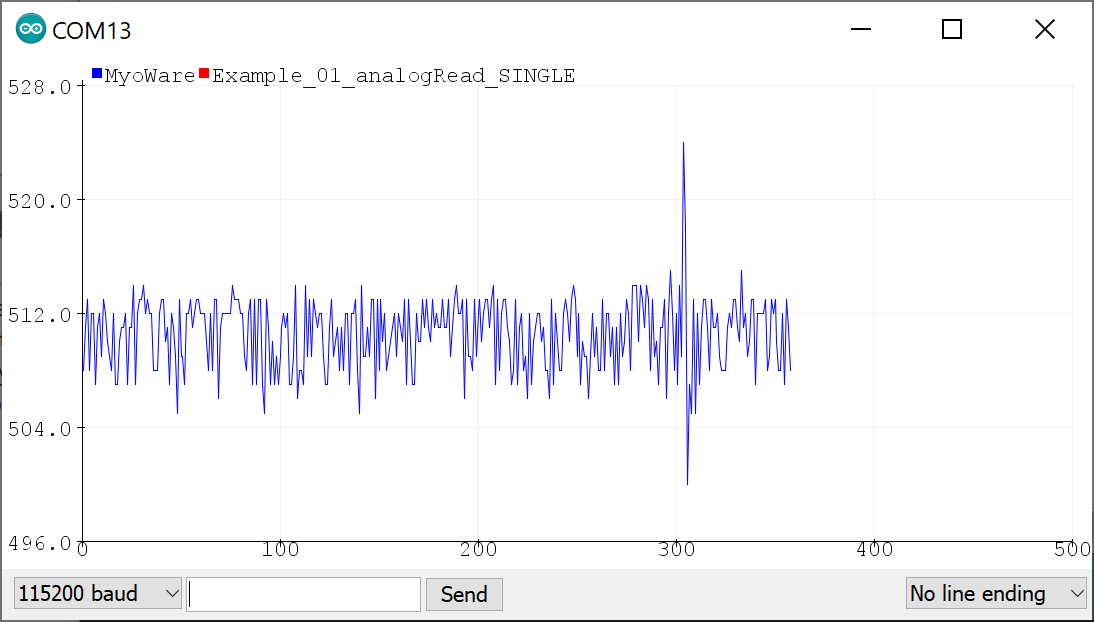 |
| Serial Plotter with Rectified Signal | Serial Plotter with Raw Signal |
Arduino Example 2: Transmitting Sensor Data via Bluetooth® - Single Sensor
The following example requires two RedBoard Artemis boards to send and receive sensor data from one muscle sensor. This is useful for users that need a clean signal or want to transmit the sensor data wirelessly.
For an explanation of how the Bluetooth peripheral and central devices works, we recommend looking at the Arduino reference language under the ArduinoBLE Library for a quick introduction.
Example 2a: Bluetooth Peripheral "Send"
The following example uses a RedBoard Artemis to transmit the analog reading wirelessly via Bluetooth. If you have not already, select your Board (in this case the RedBoard Artemis), and associated COM port. Copy the code below and paste into your Arduino IDE. Then upload the code to the board.
/*
MyoWare Sensor BLE Peripheral SINGLE SENSOR Example
SparkFun Electronics
Pete Lewis
3/17/2022
This example reads a single MyoWare Muscle Sensor, and then gets that data from this RedBoard Artemis
(the peripheral) to a second RedBoard Artemis (the central) over BLE.
This Artemis, aka the "BLE Peripheral", will read the sensor on A0.
It will then update the value to the "bluetooth bulletin board."
Note, in BLE, you have services, characteristics and values.
Read more about it here:
https://www.arduino.cc/reference/en/libraries/arduinoble/
Note, before it begins reading the ADC and updating the data,
It first sets up some BLE stuff:
1. sets up as a peripheral
2. sets up a service and characteristic (the data)
-Note, Services and characteristics have custom 128-bit UUID,
-These must match the UUIDs in the code on the central device.
3. advertises itself
In order for this example to work, you will need a second Artemis, and it will
need to be programmed with the provided code specific to being a central device,
looking for this specific peripheral/service/characteristic.
Note, both the service and the characteristic get unique UUIDs
(even though they are extremely close to being the same thing in this example)
The second Artemis, aka the "BLE Central," will subscribe to the first board's
characteristic, and check to see if the value has been updated. When it has been
updated, it will print the value to the serial terminal.
Hardware:
MyoWare Sensor with Link Shield snapped on top.
TRS cable from Link Shield to A0 port of Arduino Shield.
Arduino Shield pressed into RedBoard Artemis.
USB from Artemis to Computer.
** For consistent BT connection follow these steps:
** 1. Reset Peripheral
** 2. Wait 5 seconds
** 3. Reset Central
** 4. Enjoy BT connection
**
** ArduinoBLE does not support RE-connecting two devices.
** If you loose connection, you must follow this hardware reset sequence again.
This example code is in the public domain.
*/
BLEService sensorDataService("19b10000-e8f2-537e-4f6c-d104768a1214"); // BLE Service named "sensorDataService"
// BLE Data Characteristic - custom 128-bit UUID, readable, writable and subscribable by central
// Note, "BLENotify" is what makes it subscribable
BLEByteCharacteristic dataCharacteristic("19b10001-e8f2-537e-4f6c-d104768a1214", BLERead | BLEWrite | BLENotify);
const int ledPin = LED_BUILTIN; // pin to use for the LED
void setup()
{
Serial.begin(115200);
while (!Serial); // optionally wait for serial terminal to open, useful with micros that have native USB
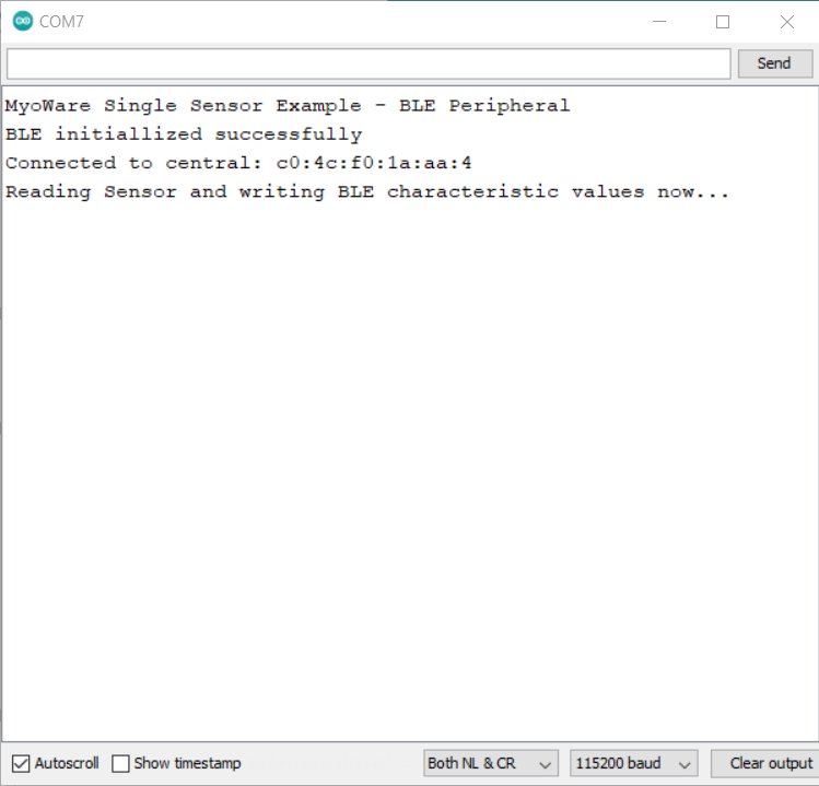
Serial.println("MyoWare Single Sensor Example - BLE Peripheral");
pinMode(ledPin, OUTPUT); // set LED pin to output mode
if (!BLE.begin()) { // begin initialization
Serial.println("starting BLE failed!");
while (1);
}
Serial.println("BLE initiallized successfully");
BLE.setLocalName("MYOWARE1"); // set advertised local name
BLE.setAdvertisedService(sensorDataService); // set advertised service UUID
sensorDataService.addCharacteristic(dataCharacteristic); // add the characteristic to the service
BLE.addService(sensorDataService); // add service
dataCharacteristic.writeValue(0); // set the initial value for the characeristic
BLE.advertise(); // start advertising
}
void loop()
{
BLEDevice central = BLE.central(); // listen for BLE peripherals to connect
if (central) // if a central is connected to peripheral
{
Serial.print("Connected to central: ");
Serial.println(central.address()); // print the central's MAC address
Serial.println("Reading Sensor and writing BLE characteristic values now...");
// while the central is still connected to peripheral:
while (central.connected())
{
int val_int = analogRead(A0); // Read the sensor attached to Analog Pin A0
byte val_byte = map(val_int, 0, 1023, 0, 255); // map the int to a byte
delay(10);
dataCharacteristic.writeValue(val_byte); // "post" to "BLE bulletin board"
// Note, because our second Artemis in this example (the central) is subscribed to this characteristic,
// it can simply call Characteristic.valueUpdated() to see if it has been updated.
// valueUpdated() will return True if updated, or false if no update has happened.
// If it has been updated, the central Artemis can read the latest value using Characteristic.readValue();
}
Serial.print(F("Disconnected from central: ")); // when the central disconnects, print it out
Serial.println(central.address());
}
}
Example 2b: Bluetooth Central "Receive"
The following example uses a RedBoard Artemis to receive the analog reading from the peripheral RedBoard Artemis wirelessly via Bluetooth. If you have not already, select your Board (in this case the RedBoard Artemis), and associated COM port. Copy the code below and paste into your Arduino IDE. Then upload the code to the board.
/*
MyoWare Receiver BLE Central SINGLE SENSOR Example
SparkFun Electronics
Pete Lewis
3/17/2022
This example sets up a SparkFun RedBoard Artemis as a BLE central device,
Then, it connects to a second Artemis peripheral device that is reading a single MyoWare
Muscle sensor. It then streams the data on the Serial Terminal.
Note, in BLE, you have services, characteristics and values.
Read more about it here:
https://www.arduino.cc/reference/en/libraries/arduinoble/
Note, before it begins checking the data and printing it,
It first sets up some BLE stuff:
1. sets up as a central
2. scans for any peripherals
3. Connects to the device named "MYOWARE1"
4. Subscribes MYOWARE1's data characteristic
In order for this example to work, you will need a second Artemis, and it will
need to be programmed with the provided code specific to being a peripheral device,
and advertising as MYOWARE1 with the specific characteristic UUID.
Note, both the service and the characteristic get unique UUIDs
(even though they are extremely close to being the same thing in this example)
This Artemis, aka the "BLE Central," will subscribe to the peripheral board's
characteristic, and check to see if the value has been updated. When it has been
updated, it will print the value to the serial terminal.
Hardware:
SparkFun RedBoard Artemis
USB from Artemis to Computer.
** For consistent BT connection follow these steps:
** 1. Reset Peripheral
** 2. Wait 5 seconds
** 3. Reset Central
** 4. Enjoy BT connection
**
** ArduinoBLE does not support RE-connecting two devices.
** If you loose connection, you must follow this hardware reset sequence again.
This example code is in the public domain.
*/
void setup()
{
Serial.begin(115200);
while (!Serial); // optionally wait for serial terminal to open, useful with micros that have native USB
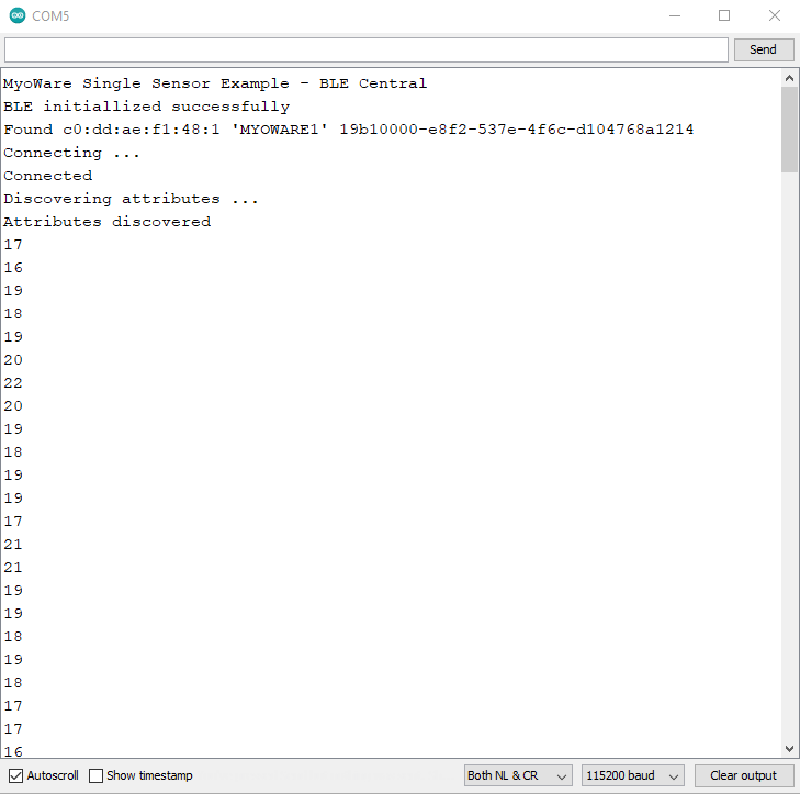
Serial.println("MyoWare Single Sensor Example - BLE Central");
if (!BLE.begin()) // initialize the BLE hardware
{
Serial.println("starting BLE failed!");
while (1);
}
Serial.println("BLE initiallized successfully");
BLE.scanForUuid("19b10000-e8f2-537e-4f6c-d104768a1214"); // start scanning for peripherals
}
void loop()
{
BLEDevice peripheral = BLE.available(); // check if a peripheral has been discovered
if (peripheral) // discovered a peripheral, print out its info
{
Serial.print("Found ");
Serial.print(peripheral.address());
Serial.print(" '");
Serial.print(peripheral.localName());
Serial.print("' ");
Serial.print(peripheral.advertisedServiceUuid());
Serial.println();
if (peripheral.localName() != "MYOWARE1")
{
return;
}
BLE.stopScan();
checkUpdate(peripheral);
Serial.println("Starting to scan for new peripherals again...");
BLE.scanForUuid("19b10000-e8f2-537e-4f6c-d104768a1214"); // peripheral disconnected, scan again
Serial.println("Scan has begun...");
}
}
// Connect to peripheral
// Then continue to check if the data has been updated,
// If so, print it to terminal
void checkUpdate(BLEDevice peripheral)
{
Serial.println("Connecting ..."); // connect to the peripheral
if (peripheral.connect())
{
Serial.println("Connected");
} else {
Serial.println("Failed to connect!");
return;
}
Serial.println("Discovering attributes ..."); // discover peripheral attributes
if (peripheral.discoverAttributes())
{
Serial.println("Attributes discovered");
} else {
Serial.println("Attribute discovery failed!");
peripheral.disconnect();
return;
}
// retrieve the data characteristic
BLECharacteristic dataCharacteristic = peripheral.characteristic("19b10001-e8f2-537e-4f6c-d104768a1214");
if (!dataCharacteristic)
{
Serial.println("Peripheral does not have that characteristic!");
peripheral.disconnect();
return;
} else if (!dataCharacteristic.canWrite())
{
Serial.println("Peripheral does not have a writable characteristic!");
peripheral.disconnect();
return;
} else if (!dataCharacteristic.canRead())
{
Serial.println("Peripheral does not have a readable characteristic!");
peripheral.disconnect();
return;
} else if (!dataCharacteristic.canSubscribe())
{
Serial.println("Characteristic is not subscribable!");
peripheral.disconnect();
return;
} else if (!dataCharacteristic.subscribe())
{
Serial.println("subscription failed!");
peripheral.disconnect();
return;
}
while (peripheral.connected()) // while the peripheral is connected
{
if (dataCharacteristic.valueUpdated()) // Check to see if the value of the characteristic has been updated
{
byte received_val = 0;
dataCharacteristic.readValue(received_val); // note, readValue returns nothing, and needs the variable to be passed by reference
Serial.println(received_val);
}
delay(1);
}
Serial.println("Peripheral disconnected");
}
What You Should See
With two instances of the Arduino IDE open with a COM port selected for each respective board, you should see the following output in the Serial Monitor set to 115200 baud. If the Bluetooth fails to connect, try pushing the reset button on the Peripheral first, wait about 5 seconds, then hit the reset button on the Central. Once connected, the muscle sensor readings will be transmitted wirelessly to the central. Try flexing your arm to see if you can see the values increase.
 |
 |
| Debug Output from Peripheral Device | Debug Output from Central Device |
For users looking for a graphical view of the output, close the Arduino Serial Monitor for the Bluetooth set as the Central device (i.e. the RedBoard Artemis receiving the sensor data). Then open the Arduino Serial Plotter. You should see something similar to the output below. In this case, we flexed our forearm muscle causing the values to increase. Relaxing the muscle caused the values to decrease.
วิธีการชำระเงิน
ชำระเงินค่าสินค้าโดยการโอนเงินเข้าบัญชีธนาคาร KBANK, SCB, BBL,TMB
กรุณาเก็บหลักฐานการโอนเงินของท่านไว้เพื่อแจ้งการชำระเงินด้วยค่ะ
ท่านสามารถแจ้งการชำระเงินผ่านระบบอัตโนมัติได้โดย Click Link ข้างล่างค่ะ
https://www.arduitronics.com/informpayment
ชำระเงินผ่านธนาคาร


@rfm0967y
ติดต่อสอบถาม
Join เป็นสมาชิกร้านค้า
MEMBER
