
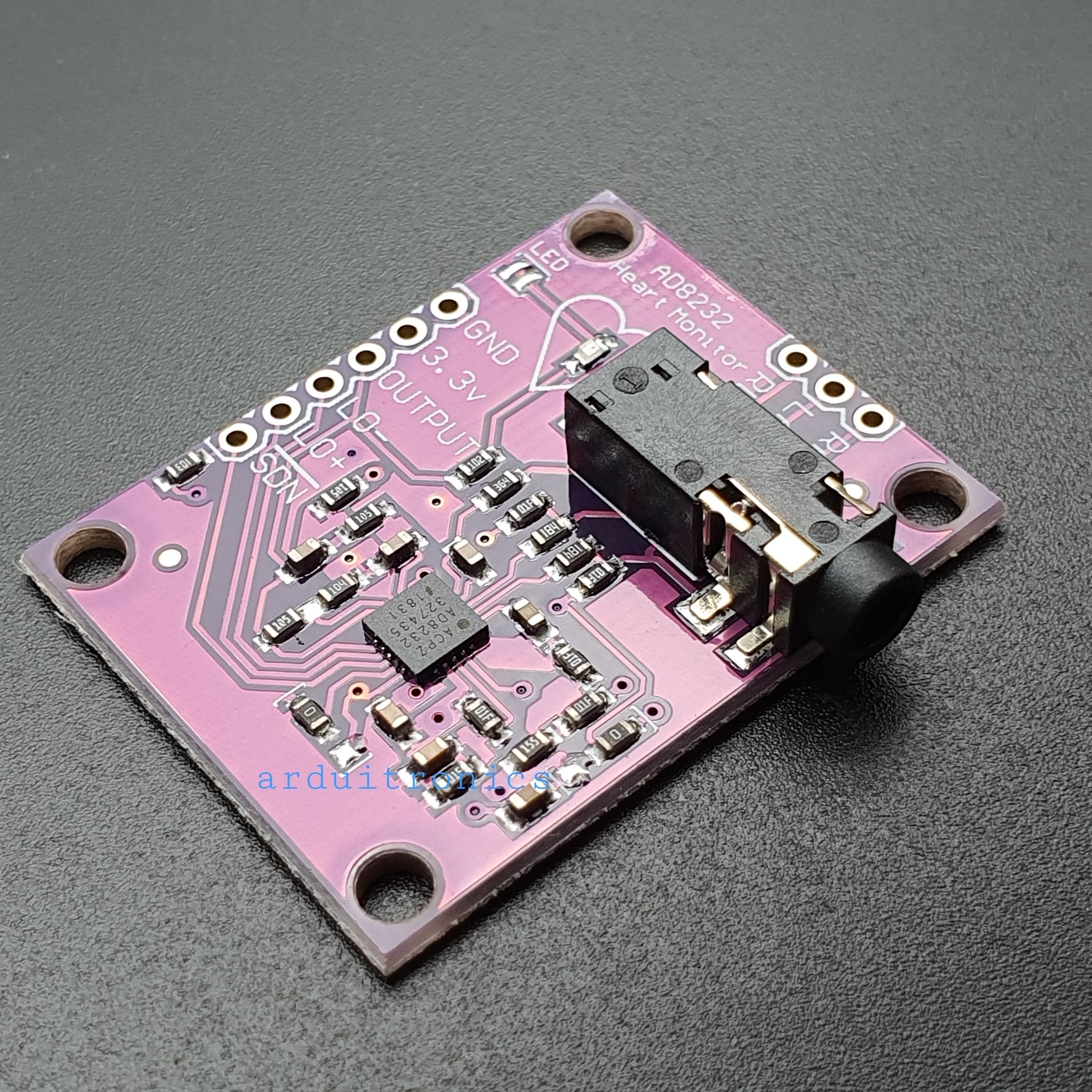
AD8232 Breakout (PCB สีม่วง) for Electrocardiogram (ECG) Heart Rate Monitor (ยังไม่บัคกรี)

| รหัสสินค้า | AS00386 |
| หมวดหมู่ | โมดูลเซ็นเซอร์ทางชีวภาพ Biometrics Sensor |
| ราคา | 285.00 บาท |
| สถานะสินค้า | พร้อมส่ง |
| จำนวน | ชิ้น |

รายละเอียดสินค้า
- Fitness and exercise heart rate monitoring
- Portable ECG
- Remote health monitoring
- Game peripherals
- Bioelectric signal acquisition
1 HPDRIVE High-pass driver output. HPDRIVE should be connected to the capacitor in the first high-pass filter.
AD8232 drives this pin to keep HPSENSE at the same level as the reference voltage.
2 +IN Positive input of instrumentation amplifier. +IN is usually connected to the left arm (LA) electrode.
3 −IN The negative input terminal of the instrumentation amplifier. −IN is usually connected to the right arm (RA) electrode.
4 RLDFB Right leg drive feedback input terminal. RLDFB is the feedback pin of the right leg drive circuit.
5 RLD Right leg drive output terminal. The drive electrode (usually the right leg) should be connected to the RLD pin.
6 SW Fast recovery switch pin. This pin should be connected to the output of the second high-pass filter.
7 OPAMP+ Operational amplifier non-inverting input terminal.
8 REFOUT Reference voltage buffer output terminal. The instrumentation amplifier output refers to this potential.
REFOUT should be used as a virtual ground at any point in the circuit where a reference signal is needed.
9 OPAMP− Inverting input terminal of operational amplifier.
10 OUT Operational amplifier output terminal. This output provides a fully conditioned heart rate signal.
OUT can be connected to the input terminal of the ADC.
11 LOD− The lead falls off the output of the comparator. In the DC lead-off detection mode, when disconnected from the −IN electrode,
LOD− is in a high level state, otherwise it is in a low level state. In the AC lead-off detection mode, LOD− is always in the low state.
The lead falls off the output of the comparator. In the DC lead-off detection mode, when the +IN electrode is disconnected, LOD+ is in a high level state,
otherwise it is in a low level state. In the AC lead-off detection mode, when the −IN or +IN electrode is disconnected, the LOD+ is at a high level.
When both electrodes are connected, they are in a low level state.
12 LOD+
13 SDN Shutdown control input terminal. Drive SDN to a low level to enter a low-power shutdown mode.
14 AC/DC lead off mode control input terminal. For the DC lead-off mode, the AC/DC pin should be driven to a low level.
For the AC lead-off mode, the AC/DC pin should be driven to a high level.
15 FR Fast recovery control input. Driving FR to a high level enables the fast recovery mode; otherwise, it should be driven to a low level.
16 GND Power ground.
17 +VS Power supply pin.
18 REFIN Reference voltage buffer input terminal. REFIN (high impedance input pin) can be used to set the level of the reference voltage buffer.
19 IAOUT Instrumentation amplifier output pin.
20 HPSENSE High-pass detection input of instrumentation amplifier.
HPSENSE should be connected to the R and C nodes that set the corner frequency of the DC blocking circuit.
EP Exposed Pad. The exposed pad should be connected to GND or left unconnected.
The electrocardiogram (ECG or EKG) is a diagnostic tool that is routinely used to assess the electrical and muscular functions of the heart.
The electrocardiogram (ECG) has grown to be one of the most commonly used medical tests in modern medicine. Its utility in the diagnosis of a myriad of cardiac pathologies ranging from myocardial ischemia and infarction to syncope and palpitations has been invaluable to clinicians for decades.
AD8232 bipolar high-pass filter to eliminate motion artifacts and electrode half-cell potential. The filter is tightly coupled with the instrumentation amplifier architecture, enabling a single-stage high gain and high-pass filter, thereby saving space and cost.
Note: This product is NOT a medical device and is not intended to be used as such or as an accessory to such nor diagnose or treat any conditions.
Application
- Fitness and exercise heart rate monitoring
- Portable ECG
- Remote health care
- Gaming peripherals
- Biological signal acquisition
Features
- Designed to extract, amplify, and filter small biopotential signals in the presence of noisy conditions, such as those created by motion or remote electrode placement.
- Single Lead Heart Rate Monitor is a cost-effective board used to measure the electrical activity of the heart.
- AD8232 is an integrated signal conditioning block for ECG and other biopotential measurement applications.
- ECGs can be extremely noisy, the AD8232 Single Lead Heart Rate Monitor acts as an op amp to help obtain a clear signal from the PR and QT Intervals easily.
- This electrical activity can be charted as an ECG or Electrocardiogram and output as an analog reading.
Specifications
- Rated temp range: 0 to 70℃
- Working temp range: -40 to 85℃
Packing List
1 x ECG sensor module
1 x EMG connecting cable
3 x Surface electrodes
Documents
- Schematic
- Eagle Files
- Hookup Guide
- Datasheet (AD8232)
- GitHub (Design Files & Example Code)
- Product Video
Connect to Arduino
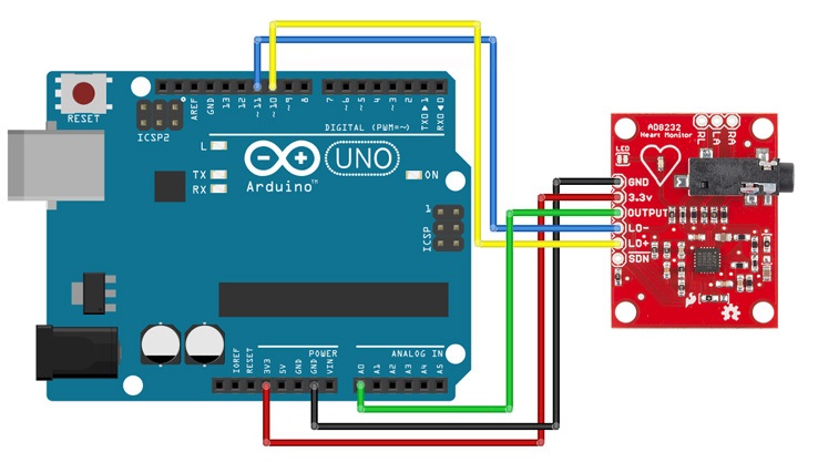
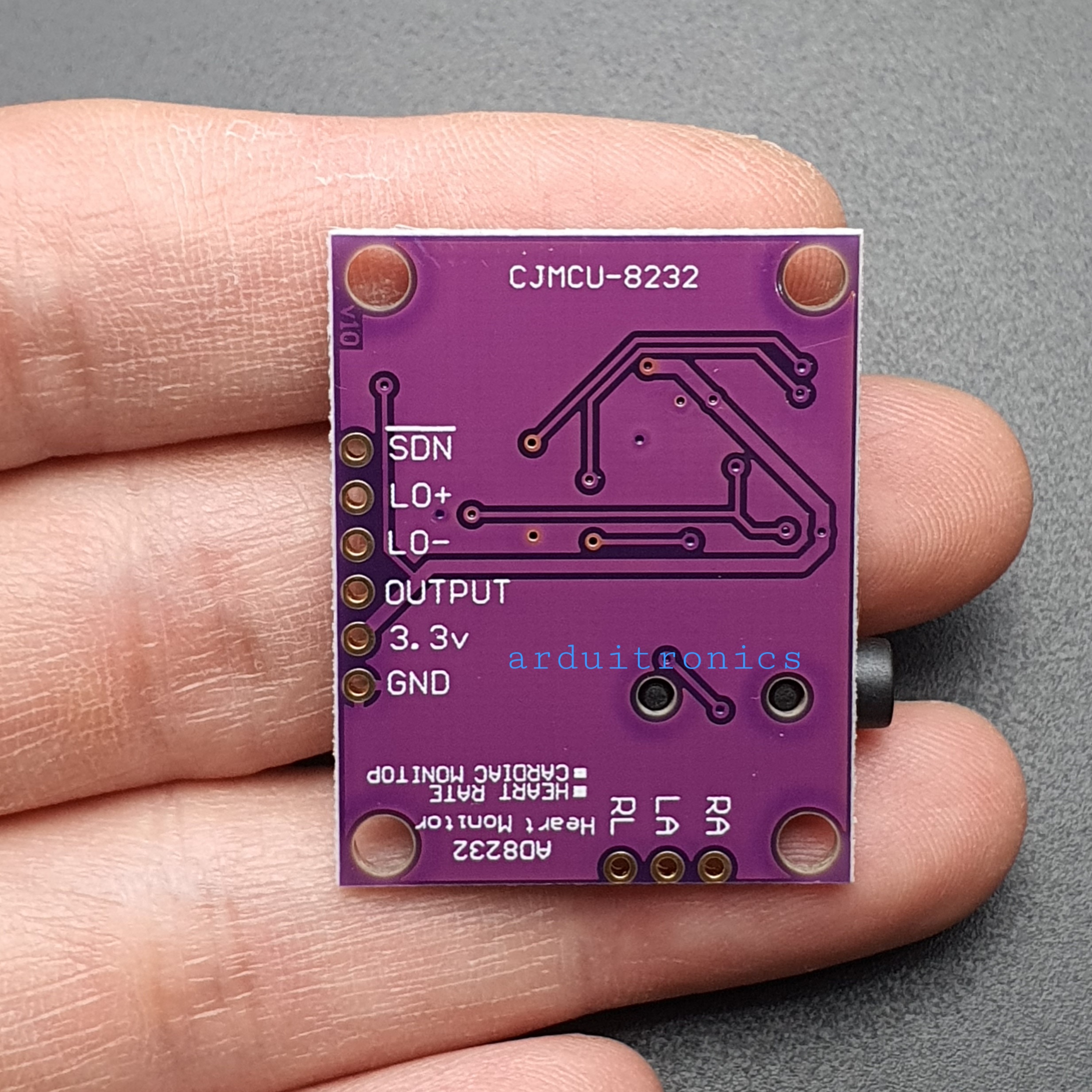
| Board Label | Pin Function | Arduino Connection |
|---|---|---|
| GND | Ground | GND |
| 3.3v | 3.3v Power Supply | 3.3v |
| OUTPUT | Output Signal | A0 |
| LO- | Leads-off Detect - | 11 |
| LO+ | Leads-off Detect + | 10 |
| SDN | Shutdown | Not used |
Tutorial & Arduino Sketch
https://learn.sparkfun.com/tutorials/ad8232-heart-rate-monitor-hookup-guide
วิธีการชำระเงิน
ชำระเงินค่าสินค้าโดยการโอนเงินเข้าบัญชีธนาคาร KBANK, SCB, BBL,TMB
กรุณาเก็บหลักฐานการโอนเงินของท่านไว้เพื่อแจ้งการชำระเงินด้วยค่ะ
ท่านสามารถแจ้งการชำระเงินผ่านระบบอัตโนมัติได้โดย Click Link ข้างล่างค่ะ
https://www.arduitronics.com/informpayment
ชำระเงินผ่านธนาคาร


@rfm0967y
ติดต่อสอบถาม
Join เป็นสมาชิกร้านค้า
MEMBER
