|
Data Sheet :openenergymonitor.org/emon/sites/default/files/SCT013-000_datasheet.pdf
CT sensors - Interfacing with an Arduino
 
http://openenergymonitor.org/emon/node/58
To connect up a CT sensor to an arduino, the output signal from the CT sensor needs to be conditioned so that it meets the input requirements of the arduino analog inputs: a positive voltage between 0V and the ADC reference voltage.
Note: This page give the example of an Arduino board working at 5 V and of the EmonTx working at 3.3 V. Make sure you use the right supply voltage and bias voltage in your calculations that correspond to your setup.
This can be achieved with the following circuit which consists of two main parts:
1) The CT sensor and burden resistor
2) The biasing voltage divider (Rvd)
Resistors R2 and R1 form the voltage divider that scales down the power adapter AC voltage and resistors R3 and R4 provide the voltage bias. Capacitor C1 provides a low impedance path to ground for the a.c. signal.
R1 and R2 need to be chosen to give a peak-voltage-output of around 1V, for an AC-AC adapter with an AC 9V RMS output a resistor combination of 10k for R1 and 100k for R2 would give a suitable output:
peak-voltage-output = R1 / (R1 + R2) x peak-voltage-input = 10k / (10k + 100k) x 12.7V = 1.15V
Improving the quality of the bias source
The relatively simple voltage bias source illustrated in “Measuring AC Voltage with an AC to AC power adapter” does have some limitations if high accuracy is required, it can be improved by adding an operational amplifier. The op.amp functions as a voltage follower, and buffers the mid-point voltage that appears at the junction of R3 & R4. This significantly reduces the impedance of the voltage source, resulting in enhanced performance.
Only one op.amp is needed, the current sensors can share the bias supply and connect to amplifier output (“mid-point”) with little fear of interaction between the inputs (which can be troublesome in some circumstances).

Notes:
- this modification might not be suitable where the power source is batteries,
- any pair of equal resistors up to 100 kΩ may be used for R3 & R4, and C1 can be reduced to 100 nF for resistor values at the high end of the range.
Calculating a suitable burden resistor size
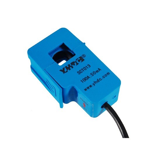
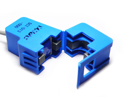
If the CT sensor is a current output type such as the YHDC SCT-013-000, the current signal needs to be converted to a voltage signal with a burden resistor. If its a voltage output CT you can skip this step and miss out the burden resistor as the burden resistor is already built in to the CT.
1) Choose the current range you want to measure
The YHDC SCT-013-000 CT has a current range of 0 to 100A so for this example lets choose 100A as our maximum current.
2) Convert maximum RMS current to peak-current by multiplying by sqrt(2).
Primary peak-current = RMS current x sqrt(2) = 100A x 1.414 = 141.4A
3) Divide the peak-current by the number of turns in the CT to give the peak-current in the secondary coil.
The YHDC SCT-013-000 CT has 2000 turns and so the secondary peak current will be:
Secondary peak-current = Primary peak-current / no. of turns = 141.4A / 2000 = 0.0707A
4) To maximise measurement resolution the voltage over the burden resistor at peak-current should be the arduino analog reference voltage (AREF) divided by 2
If your using an arduino running at 5V: AREF / 2 will be 5V / 2 = 2.5V and so the ideal burden resistance will be
Ideal burden resistance = (AREF/2) / Secondary peak-current = 2.5V / 0.0707A = 35.4 Ohms
35 ohm is not a common resistor value we have a choice of 39 ohms or 33 ohms. We recommend going for 33 ohms +- 1%
Tool for calculating burden resistor size, CT turns and max Irms - thanks to Tyler Adkisson for building and sharing this.
2) Adding a DC Bias
If you were to connect one of the CT (+burden) wires to ground and measured the voltage of the second relative to ground the signal would oscillate from positive to negative voltage. The Arduino requires a positive voltage only and so by connecting the end of the CT that we just connected to ground to a 2.5V level (half of the supply voltage) instead, the signal voltage will now oscillate around 2.5V and remain positive.
The resistors Rvd in the circuit diagram above make up a voltage divider that provides this 2.5V level.
Choosing a suitable value for Rvd resistors:
Higher resistance lowers quiescent energy consumption but also increases noise.
We have been using 10k resistors for mains powered monitors. The emontx uses 470k resistors to really keep the power consumption to a minimum as it is intended to run off batteries for several months.
|